|
Volare-Gypsy J-8 SU
Indoor Joined.-Wing Experimental Glider
by Alex Morillo
This is about an
experimental balsa model built to test fly it for a maximum glide
performance.
Precise Building is the first process to undertake, because
general geometry lines have to be very accurate, symmetric, and with the
least wood and glue, to keep weight down. ( 9 grams )
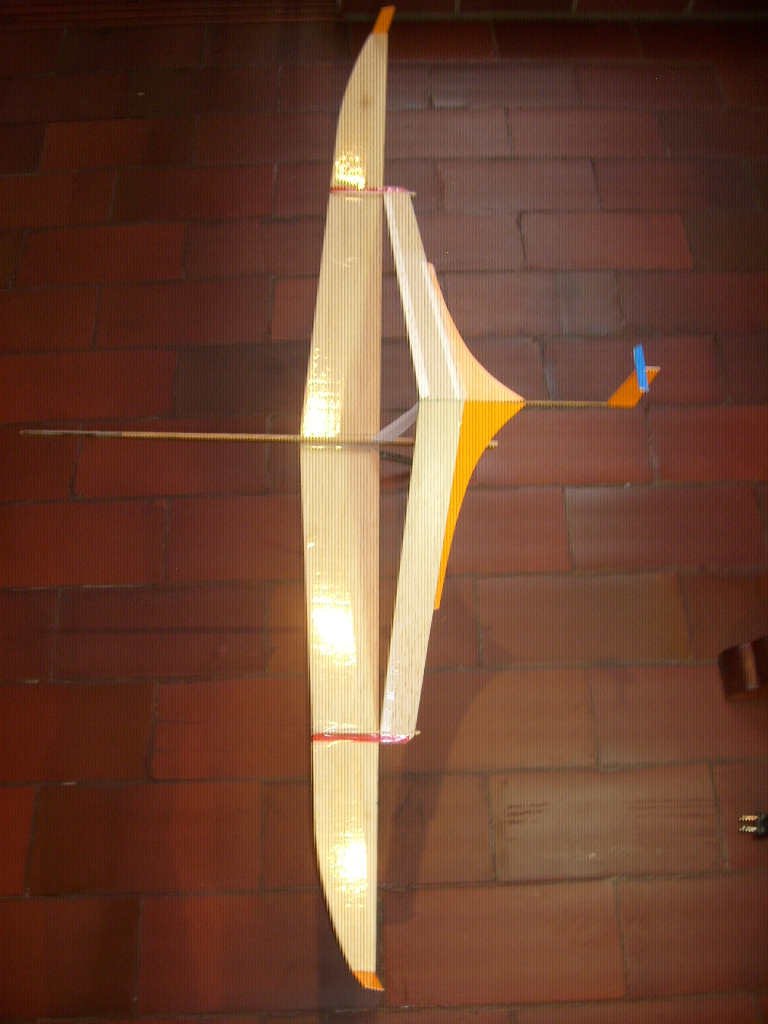
The planform is type J-8 (front wing straight and-or with less than
5 deg sweep).
The joint point is at or near the 60% span. Outer panels are with plenty
of dihedral.
Aft wings are with negative sweep and with anhedral.
Because of the
joined-wing concept, the wings self-support each other in a strong
enough structure at low enough weight for this specific type of indoor
glider.
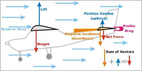
Special care is taken with Incidence angles between wings to minimize
drag.
Decalage is used for
double duty: to generate lift with the rear-upper wings
and to impart pitch-up stability (aft portion of the aft wings).
High performance aerodynamics is possible because of several careful
details:
Flat Airfoils, with very little frontal area (the aft wing is only
1 mm thick )
and fly at very little AoA.
The rear wings act as lift-wings (fore portion) and also because
they are
set at low negative AoA, as a horizontal-stab tail, to provide pitch-up
stability
A very small trim tab is glued on top of the rudder for trimming.
High aspect
ratio wings are use as well as high spans for
minimizing Induced
drag.
Winglets are also used
to minimize tip vortexes.
Very low wing
loadings of near 1,125 grams per sq dm.
Could be lighter , with more detail craftsmanship.
Flat Surfaces with selective
boundary
layer control (BLC) meaning that all
surfaces are partially covered with glossy, low-drag, clear plastic tape.
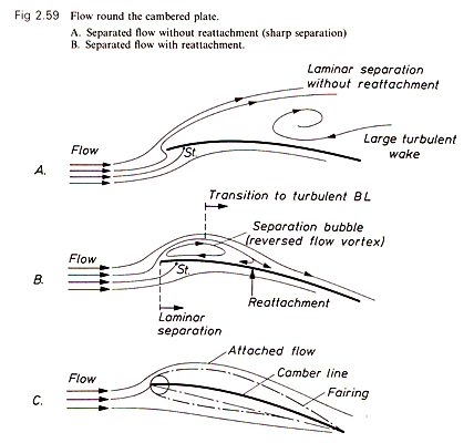
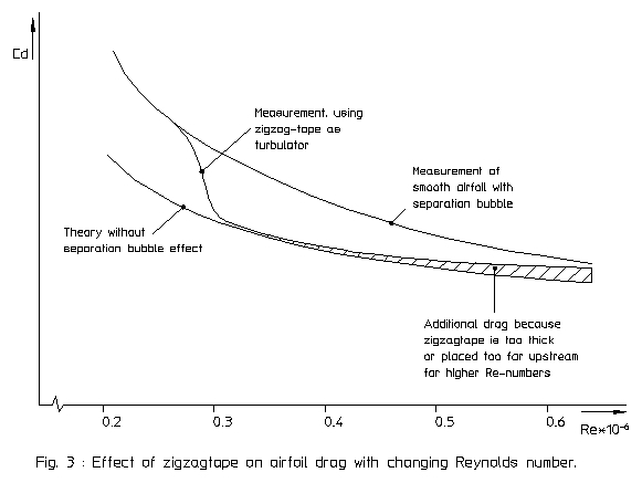
The initial laminar
airflows tends to become turbulent at some point over the
chord of wings; therefore , clear tape is only adhered to the point
where it is
believed to be the transition area from laminar-to-turbulent flow.
The airflows over
raw balsa are tripped and
reinvigorates the boundary layer
(about 1 mm thick?) so flow re-attaches to the wing as a stable-turbulent
airflow with minimal drag consequences.
Another added benefit with this selective tape is that as the airflows get
wider (higher) over certain areas, in such a way, that the flat airfoils
gain some induced camber which improves the performance of the wings.
If this BLC is used on lower surfaces, it,s effect helps deflect airflows
downward
near the under-surface of the Trailing edge, perhaps as split flaps would
do.
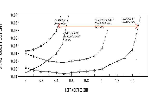
Airflows on this glider, are at very low Reynolds Number, so viscous
forces are
dominant,
therefor, clear tape to let air slip-slide effortless at front and to BLC
farther aft
on any surface, like wings and rudder.
The glider is more, or less designed to fly at one speed , after the
initial hand
launched acceleration. That speed has to be found, and/or calibrated for
maximum
glide (L/D) at its highest speed possible, mostly due to very low drag
from the glider itself.
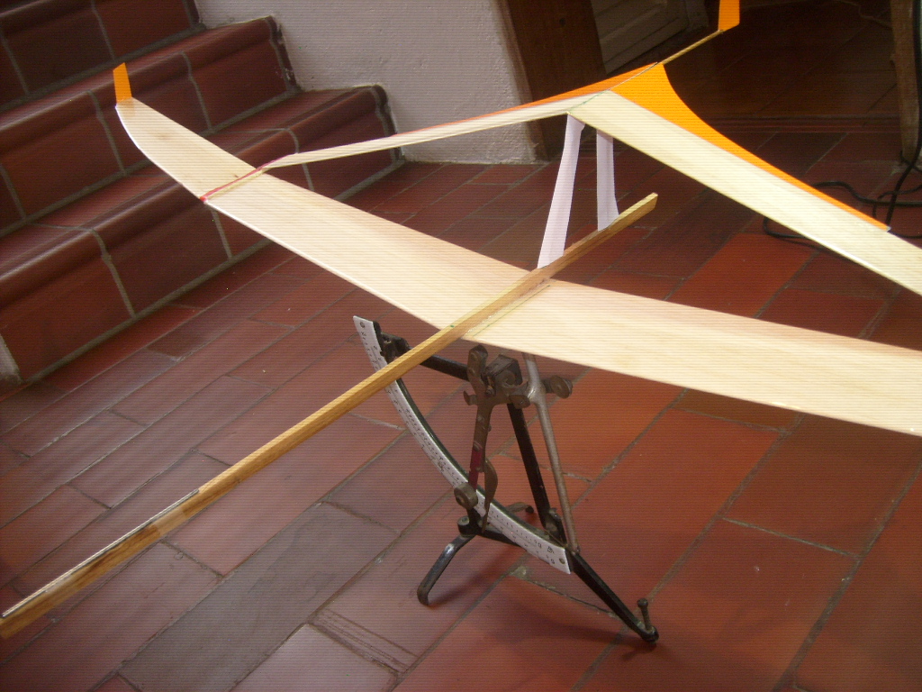
The low wing loading was only possible by placing a thin steel rod WAY
forward
on the keel, so that by its long arm (leverage)
the right CG location can be attained; notice that the CG is around 55%
chord.
Careful selection of wing planform shapes were used, like tapered wing tip
portions.
The joint is a non-overlapping type for
optimizing drag reduction of drag due to possible
Venturi effects. On this glider structural issues are secondary.
Self-leveling and efficient straight glides are possible with the
robust-dihedral wings.
Great glides confirm that this system works; but I need to test it more.
Amorillo61@yahoo.com
I only take credit for the three pics of the glider; the other images
belong to others for reference only during this study. |

|