Free Rotor
I WONDER IF THIS Colin Jack is also COLIN
BRUCE. Colin Bruce JACK. Yes.
Not sure yet what to do with the "Humphry" (without "e" that is shown in the
1992 patent. Yes.
http://emits.esa.int/emits/owa/loadfiles.showfile?p_file=17933%2FEntityDescription.doc
Oxford Mathematical Designs (since 1980s)
Oxford Mathematical Designs Ltd. VAT
number 434 5601
Surface-to-air refueling study done for the UK’s Ministry Of Defence.
Also a science book author under pen name Colin Bruce and software author.
Inventor.
COLIN BRUCE JACK
(preferred naming)
Degree in Mathematical Physics, Sussex University in 1978.
Book writing and research. Three books on mathematics and physics.
One is on quantum physics, published by the US National Academy of
Science’s Joseph Henry Press.
"I am the inventor of several
potentially disruptive engineering concepts, including a type of wind turbine
called the Free Rotor which was offered a development grant by the UK’s
Energy Technology Support Unit
ETSU,
a computer control device called the Baton which anticipated the Nintendo
Wii
by over a decade, and several space propulsion concepts. I have done research
for the European Space Agency on a space propulsion concept I invented in the
1980s, the solar kite. "
PUBLICATIONS: PAPERS & ARTICLES
Solar Sails And Kites (article) Spaceflight, November 1994, Vol. 36 No. 11,
p382-384
The EPR Paradox (article) Physics World, April 1995, Vol. 8 No 4, p39-42
(subsequently adapted for a BBC World Service piece)
A Kinetic Tether System For Launching Payloads (paper, with C S Welch)
IAF-95-V.4.06 delivered at 46th International Astronautical Congress, contact
IAF for reprints
Solar Kites: Small Solar Sails With No Moving Parts (paper, with C S Welch)
IAF-96-S.4.03 delivered at 47th International Astronautical Congress
reprinted in Acta Astronautica, Jan/Apr 1997, Vol. 40 Issue 2-8, p137-142
Spacefarer Solar Kites for Solar System Exploration (with R Wall and C S
Welch)
delivered at 55th International Astronautical Congress, reprinted in
JBIS, May/June 2005, Vol 58 No. 5/6, p155-166
PUBLICATIONS: BOOKS (under pen name
Colin Bruce)
The Einstein Paradox
Originally published in the USA by Addison Wesley in 1997, subsequently
translated into over a dozen languages worldwide.
Conned Again, Watson: Cautionary Tales Of Logic, Math & Probability
Originally published in the USA by Perseus Books in 2001, subsequently
translated into over a dozen languages worldwide.
Schrödinger’s Rabbits: The Many Worlds Of Quantum
Originally published by the National Academy of Sciences’ Joseph Henry Press
in 2004; foreign editions include French, Italian, Chinese (complex),
Japanese.
=====================
Search terms: Colin Jack, Colin Bruce, Colin
Humphry, Colin Humphrey, Free Rotor, 1992020917, autogyro,
WO/1992020917 Free Rotor by JACK, Colin, Humphry, Bruce (one man).
Colin Jack. Colin Bruce.
Multi-rotors are treated.
Faired tethers are recognized. 1992.
Free Rotor
http://tinyurl.com/ColinBruceFREErotor
(WO/1992/020917) FREE ROTOR
by C JACK - 1992
Applicant: JACK, Colin, Humphry, Bruce [GB/GB]; (GB).
... Abstract: A free rotor is a structure which rotates in its entirety,
extracting kinetic energy ...
www.wipo.org/pctdb/en/wo.jsp?wo=1992020917
for original patent
document with images in PDF format From that page, click "Documents"
and then on next served page choose "Download" and choose the
PDF version.
(WO/1992/020917) FREE ROTOR
Pub. No.: WO/1992/020917 International Application No.: PCT/GB1992/000904
Publication Date: 26.11.1992 International Filing Date: 18.05.1992
Chapter 2 Demand Filed: 18.12.1992
IPC: F03B 17/06 (2006.01), F03D 11/04 (2006.01)
Applicant: JACK, Colin, Humphry, Bruce [GB/GB]; (GB).
Inventor: JACK, Colin, Humphry, Bruce; (GB).
Priority Data: 9110791.2 18.05.1991 GB
9111437.1 28.05.1991 GB
9118385.5 28.08.1991 GB
Title: FREE ROTOR
Abstract: A free rotor is a structure which rotates in its entirety,
extracting kinetic energy from a flow in which it is immersed in such a way
that there is no net torque force on it. It is connected via a
counter-rotating joint (U) to a mooring tether (V). The structure is tilted
so that the drag force on the rotor is directed upward of the horizontal,
providing a lift force which prevents the tension in the tether dragging the
structure downward and may also support its weight against gravity.
Electrical energy may be generated by means of secondary propellors (L, M, N)
mounted on the structure at points outward from the centre and forced through
the surrounding medium at high speed by its rotation. The primary
implementation envisaged is an airborne wind generator.
=========================OCR TEXT has errors compared
to the
PDF format, which
see.
Claims:
WO 1992020917 19921126
CLAIMS
1. A structure rotates as a rigid unit, in so doing extracting momentum and
kinetic energy from a flow of air or water in which it is immersed, without
any net torque force being exerted on it by the said flow; its only external
connexion is to a tether which transmits no torque force and which joins a
point on the axis of rotation to a fixed anchorage point below and up-flow of
it; the reaction force on the rotor is arranged to be inclined with respect
to the flow direction, providing a vertical force component which prevents
the tension in the tether dragging the structure downward and may also
provide an additional net lift force.
2. A structure as claimed in claim 1, further characterized in that tensile
members (Fig 1: 0,P,Q) from the rotor blades (Fig 1: I,J,K) to the central
axis transmit the induced loads on the rotor blades efficiently to the
central axis.
3. A structure as claimed in claim 1, further characterized in that at the
rotating joint where the rotating portion of the structure connects to the
non-rotating mooring tether there is provided a joint with a powered motor
(Fig 1: U) which counter-rotates the joint so as to prevent any part of the
mooring tether becoming twisted.
4. A structure as claimed in claim 1, further characterized in that it is
airborne and driven by the wind.
5. A structure as claimed in claim 4, further characterized in that
electrical power is generated by means of secondary rotors placed at points
on the structure outward from the axis of rotation and driven* through the
surrounding air at high speed by the structure's rotation.
6. A structure as claimed in claim 5, further characterized in that the
secondary rotors are of a type whose axis is normal to the incident airflow,
and which are arranged so their axes of rotation are parallel to that of the
main structure (Fig 2c) .
7. A structure as claimed in claim 5, further characterized in that the
secondary rotors are of a type whose axis is parallel to the incident
airflow.
8. A structure as claimed in claim 5, further characterized in that the pitch
of the main rotor blades can be varied so that the structure turns at a
substantially constant rate in all wind speeds, so enabling fixed pitch
secondary rotors to be driven at a constant speed.
9. A structure as claimed in claim 4, further characterized in that the
structure constitutes a self-levitating autogyro; when the wind drops the
structure is forced to continue rotating and flies as a powered helicopter.
10. A structure as claimed in claim 4, further characterized in that a
central lighter-than-air balloon lifts the structure against gravity.
11. A structure as claimed in claim 10, further characterized in that the
central balloon is substantially spherical.
12. A structure as claimed in claim 11, further characterized in that the
airflow over the central balloon is made turbulent so as to decrease the dreg
on it.
13. A structure as claimed in claim 4, further characterized in that the
device can be controlled in orientation and/or in altitude by altering the
pitch of the rotor blades individually.
14. A structure as claimed in claim 4, further characterized in that the
rotor blades are of biplane form (Fig 2d) .
15. A structure as claimed in claim 4, further characterized in that it
diminishes or deflects the wind for the purpose of weather or climate
control.
16. A structure as claimed in claim 1, further characterized in that it is
immersed in water and driven by a current of water.
17. A structure as claimed in claim 16, further characterized in that
electrical power is generated by means of secondary rotors placed at points
on the structure outward from the axis of rotation and driven through the
surrounding water at high speed by the structure's rotation.
18. A structure as claimed in claim 16, further characterized in that it
diminishes or deflects an ocean current for the purpose of weather or climate
control.
=======================================
OCR text
Description:
WO 1992020917 19921126
FRE E ROTOR DESCRIFΠON
Wind generators are a clean source of energy. However existing designs are
inherently poor in several respects. Power is generated in the form of a very
large torque force acting on a large propellor (or other rotor) turning at
low rpm. Massive bearings and gears are required to hold the rotor in place
and convert its motion to power. Heavy structural demands are made on both
the rotor blades and the support tower. Capital and maintenance costs are
therefore high.
According to the present invention is provided a wind generator which is
lighter, cheaper and requires less maintenance than existing designs. The
essential feature of the design is that a rotating structure (which may take
the form of a propellor similar to that of a conventional horizontal-axis
wind turbine, or another type of rotor) extracts energy from the wind without
the need to exert any torque or bending force on any central support. The
device may be airborne and connected to the ground only by a tethering cable.
The rotor is arranged (by tilting its axis) so that the drag force created on
it as a result of its operation is tilted upward from the horizontal,
opposing the tension in the mooring cable, and if desired also providing a
net lift force which helps support the structure against gravity.
Electricity may be generated using small rotors attached to outer points of
the main rotating structure and driven at high speed by its rotation. The
secondary rotors can be conventional propellors; or machines normally used as
vertical-axis turbines such as Cycloturbines or Savon is Rotors or Darrieus
turbines. In this case the axis of rotation of the secondaries and their
attached generators can be arranged parallel to the axis of rotation of the
main rotor, eliminating gyroscopic torque forces.
As well as generating electricity, the devices can be used for
weather/climate control. Whereas ground based wind generators within the
boundary friction layer have little net effect on the wind, airborne
generators slow the wind in which they are placed. Tilted airborne generators
induce vertical air movement, sucking air (typically moving faster and at a
lower temperature) downward from higher altitudes. By choosing which devices
to operate, and steering those devices which are operating in altitude and
veering them to left or right with respect to the incident wind, an extended
aerial wind farm can be used to exert significant control over the weather.
The temperature of an area can be controlled by steering and/or diminishing
hot or cold winds selectively; and the rainfall by steering and/or
diminishing moist and dry winds. Smog control can be performed by forcing
clean air from higher altitude down to mix with relatively static air at
ground level. Amplification effects (such as the 'butterfly effect') might
permit significant climate control even with small numbers of generators.
Note that devices deployed for climate control need not necessarily be
equipped with secondary propellors and generators for electricity
manufacture, and can therefore be cheaper.
SUBSTITUTE SHEET
A similar design to the above, but immersed in water rather than air, can
extract energy from an ocean current or tidal flow, generating electricity.
Water immersed devices can also perform climate control, in particular by
slowing and/or diverting hot or cold ocean currents, and promoting mixing of
ocean waters from different depths. A line of the devices, placed for example
across the mouth of an estuary, can constitute a 'virtual barrage' generating
a significant head tf water on the up-flow side. ,
PRIOR ART
I am aware of two previous types of zero-torque wind generator design. One
well known design uses hollow exhausting blades through which a current of
air is driven try a combination of centrifugal and Venturi forces. A second
design using secondary rotor-tip propellors is disclosed in German patent
application DE 3322589 Al .
There are many patents for airborne wind generators, most commonly for
designs similar to ground based devices but lofted by moored airship or kite.
An airship-based rotating structure design is disclosed in US Patent
4,491,739; and a similar one in US Patent 4,450,364. The most critical
distinction between the present invention and the above is that in the
present invention the rotor structure is designed to be tilted so that the
reaction force generated when the machine is operating, which is parallel to
the axis of rotation, is upwards of the horizontal and acts in opposition to
the tension in the slanting tether cable. In consequence, the lift which must
be provided by the balloon is either reduced by a factor of several or
eliminated, as in toe different examples below. The result is a practicable
generator which is relatively inexpensive and can survive high winds.
I am also aware of US 3,987,987 which discloses various airborne wind
generators based on tethered aircraft, autogyros and kites.
NOTE
The following acronyms are used in the subsequent examples:
BEAN = Bearingless End-braked Autogyro Node
STALK = Stack To Altitude LinKage
In all Figures, arrows labelled W denote wind direction unlabelled arrows
indicate direction of movement.
Note .bat throughout this patent, where reference is made to a rotor acting
like an autogyro, this refers to the fact that incident wind force causes the
rotor to spin while also giving rise to a force acting approximately along
die axis of spin. Of course the rotor may be deployed at any angle to the
wind, ranging from axis of rotation approximately at rigid: angles to wind
direction to axis of rotation approximately parallel to wind direction. In
the former case, net airflow through the rotor resolved in the axial
direction may be in a direction opposite to that of the incident wind vector
resolved in the axial direction. In the latter case, net airflow through the
rotor resolved in the axial direction may be in the same direction as the
incident wind vector resolved in the axial direction. Reference to autogyro-like
behaviour denotes a simile rather than an exact correspondence. When the axis
of rotation is almost parallel to the wind vector, die rotor acts more like
a conventional propellor than like an autogyro blade.
Note that whereas in some instances 'STALK' refers to a stack of primary
rotors, in others it denotes the system of tethers used to anchor a single
rotor to the ground.
EXAMPLE 1
This example is illustrated with respect to Figure la showing the device in
elevation and Figure lb showing the rotor in plan (in Figure la only two of
the three rotor arms are visible) in which:
The central spherical helium balloon A provides static lift which supports
the device against gravity. The balloon A is connected by a plurality of
tensile members W (only some of which are shown) to a surrounding rigid
triangle of members C, D, E, at the corners of which are attached three rotor
blades I, J, K, via joints F, G, H which hold them rigid with respect to the
central triangle but permit them to be rotated about their axes so as to vary
the pitch of each blade.
The device is attached to the mooring cable V via a rotating joint at the
connecting structure U which allows the entire structure to rotate as a unit.
The rotating joint may be actively counter-rotated by means of a small motor
to prevent the mooring cable V beoming twisted as the device spins.
Tensile members R, S, T connect the 1'nlring structure U to the central
support triangle. Additional tensile members O, P, Q (which may have a
streamlined airfoil-like cross-section, rather than circular, so as to
minimize the drag on them induced by the structure's rotation and thus minimi
TO the energy so wasted) connect directly to the rotor arms I, J, K. They
become taut when the device is operating, so greatly reducing the bending
forces which the rotor arms must be capable of withstanding, and thus their
structural weight.
The energy of rotation imparted to tiie structure by the wind is harvested by
means of small secondary propellors L, M, N connected to high-rpm
aircraft-type generators. These propellors are driven through the air at many
times the incident wind speed due to the structure's rotation. Because the
energy in an airflow is proportional to the cube of the velocity, and the
main rotor tips may be driven at up to — 12 times the incident wind speed,
relatively small secondary propellors can harvest all the energy generated.
The pitch of the primary blades is varied with wind speed to keep the rate of
rotation constant: thus the secondary propellors may be fixed in pitch yet
drive generators at constant r.p.m.
The device may be deployed at almost any location. A particularly
advantageous site is at sea over the continental shelf. The tether V then
connects to a buoy (not shown) and mooring line to the sea bed.
In a flat calm, the device hangs vertically with most of the tether V
floating on the water and the structure U a short distance above the surface.
The static lift of the balloon A is just sufficient to support the weight of
SUBSTITUTE SHEET
the structure. As the wind gets up, the structure tilts slightly and starts
to autorotate, so producing an autogyro-style lift force. (The device may
also be force-started. An electric generator is also a motor, so power can be
fed to tiie secondary propellors to initiate rotation of die device, so
providing manoeuvering control iτ-Vrι-rιing βverι m a ffø calm.) The -n~~-'tt-r'*
and orientation of the lift force may be controlled by altering the pitch of
the individual rotor blades as the device turns. In this way the mooring line
is lifted . from die water and pulled taut, and tiie device steered to the
operating position shown in Figure la. Cyclic pitch control of the rotor
blades can be used to alter tiie inclination of the axis of rotation, forcing
it a few degrees up or down from the inclination of the mooring line, and so
controlling -be altitude of the device. In particular, in very high winds, a
substantial lift force can be generated to prevent ti e drag on the central
balloon forcing the structure down into the sea.
The drag on the central balloon may be considerably reduced (from Cd=0.5 to
Cd=0.1) Toy malting the flow over its surface turbulent. Its rotation alone
may induce the necessary turbulence, or it may be assisted by roughening tiie
surface of the balloon, and/or using a balloon which is polygonal (e.g. a la
Buckminster Fuller geodesic with stiff cables or belts attached internally to
the balloon's surface, whose intersection points may also provide convenient
anchorages for tiie guy wires W) rather than perfectly spherical; and or by
attaching 'spoiler' devices to the structure; or by other means. Thus the
device can survive the most severe storms and wind gusts in situ while
continuing to operate.
The device may be built and serviced at a land-based facility, e.g. in a
dockside hangar. It may be towed to its mooring when already airborne,
allowed to autorotate as it does so, by a small boat, and recovered in the
same way.
The device is controlled by a simple autopilot (e.g. a microprocessor).
Sensing devices may include accelerometers, inclinometers, rotation sensors,
wind sensors, force sensors, altitude sensors, etc. Control may be exerted
solely by varying the pitch of the primary rotor blades or in other ways,
e.g. with aerodynamic control surfaces; varying the length of combinations of
any of the wires O, P, Q, R, S, T, W; pumpimg ballast water up and down a
pipe within the tether; etc.
The cables O, P, Q attach to the rotor arms I, J, K at tiie point on the
chord corresponding to the centre of lift, via hinges which may be recessed
into the wing surface. There may be means provided to tighten and slacken, or
jettison altogether, the cables O, P, Q and/or the cables R, S, T during
deployment and/or recovery operations, to ensure the cables O, P, Q do not
exert unwanted bending forces on the rotor arms at these times.
Lifting gas will leak from the balloon over time. This may be compensated by
including water ballast which is progressively jettisoned; or an insulated
flask of hydrogen or helium which evaporates in a controlled way to replenish
tiie lifting gas; or providing a pipe or pipes within tiie mooring tether
which can be used for pumping lifting gas and/or water ballast up to the
structure from below.
The power generated is transmitted to land down the tether (ohmic heating of
the tether cable as a side-effect will help prevent icing) and then via
seabed cable. Power will typically be generated at high frequency and
relatively low voltage; boosted to higher voltage by a transformer on the
seabed, or floating immersed attached to the mooring line for easier
recovery; transmitted to land; then transformed or inverted to reduce the
frequency to mains supply. Other combinations are of course possible: for
example the high frequency power may be inverted to DC, transmitted
efficiently to land and then across a DC land grid, and restored to AC near
the point of consumption.
Note that many detailed arrangements of the wires labelled O, P, Q, R, S, T,
W are possible, including different numbers of attachment points and choices
of attachment points to the central balloon, support triangle, and rotor
arms. Winches or hydraulic pistons may permit the lengths and tensions of any
of these wires to be varied. Additional wires may be employed, for example
connecting the rotor arms one to another, or to the central balloon, to make
the structure stronger and/or more rigid. Internal wires within the central
balloon may pull it into a puckered shape so as to make the airflow over it
more turbulent.
In a variant of the design, the rotor arms may be hinged so that they hang
vertically when the device is static, and are deployed by centrifugal force
as the device is started by forcing rotation using the secondary propellors.
In a related variant which is a purely tensile structure, the rotor inner
ends may be connected directly to the central balloon by tensile cables
without the need for a central support triangle: when the device is not
operating the blades hang vertically beneath the balloon. To avoid tangling
during deployment and recovery, tiie guy wires may be capable of being wound
in and out in synchrony with each attached to an individual electric winch at
its endpoint(s). Alternatively the guy wires may initially be held to minimum
length by ties which break open as the structure spins up, and all but the
outer guys may be jettisoned as the structure spins down for recovery.
In another variant of the design, the tensile cables R, S, T may be replaced
by rigid structural members forming a rigid tetrahedron whose vertices are F,
G, H, U.
In another variant the central rigid triangle C, D, £ may be inside rather
than outside the central balloon.
Of course there may be a greater number of rotor blades than three.
Two-bladed designs are also possible, but have poorer orientation-holding
stability against yaw and pitch forces.
The central triangle may be another structure, e.g. one having more sides
and/or members extending in the structure's axial direction rather than being
confined in a plane. Shrouds may be mounted on structural members to minimize
drag on them and hence wasted energy.
Gyroscopic forces on the propellors and their attached generators as their
axis of rotation is forced to change
SUBSTITUTE SHEET
continually by the main structure's rotation may constitute a problem. The
propellor axles may have mount points both forward and aft of the propellors
to help counter this. The propellors may as shown in Figure 2a be connected
to gears A which drive generator shafts in tiie opposite direction to ti e
propellors so minimizing the net angular momentum and hence the gyro torque
force the system exertson its mount.
Secondary propellors may be mormte m counter-rotating pairs. Or a plurality
of small propellors may be used in place of each secondary propellor. Due to
their higher rotation speed, these can be mounted each on the same axle as
its generator, with no gear transmission. Half tiie small propellors in each
assembly rotate clockwise, the rest anticlockwise.
Propellors (Fig 2b) whose axis is parallel to in incident airflow may be
attached to gears A which drive generator shafts B at right angles, thus the
attached generators C may be aligned with their spin axis parallel to the
spin of the main structure.
If the secondary propellors are mounted near tiie tips of tiie primary rotor
blades and their direction of rotation is correctly chosen, they may interact
beneficially with the airflow over the primary blades by cutting down the
airspill over the ends of tiie primary blades and minimizing the tip vortices
thus created.
Conventional propellors may be mounted on the rotor blades with their axes of
rotation parallel to the structure's spin axis if deflector plates around
tiie propellors deflect the surrounding airflow through them.
In another variant of tiie design, tiie central balloon is omitted, and the
autogyro-like lift provided by the rotaϋon of the rotor keeps its weight
airborne. When the wind drops, power supplied from the land drives the
secondary propellors to force the structure to continue rotating so it
continues to fly but in a helicopter-like manner.
h another variant of the design the central rigid triangle is omitted and the
rotor blades attach directly to the central balloon which is either inflated
to sufficiently high pressure to itself act as a compressive structural
member and or reinforced with internal compressive members. The balloon may
take an axially elongated form (more like an airship) extending as far as the
joint U, and the wires O, P, Q may attach to the airship hull. Additional
wires from the rotor arms to the aft end of the hull may help prevent them
bending downward when the device is not operating and its axis is vertical.
Cross-wires from points on the rotor arms to points on the circumference of
the airship hull may help secure the rotor arms against sideways movement.
In another variant of the design the rotor blades have biplane form, thus
improving their ability to withstand bending forces at the expense of
aerodynamic efficiency. This may make it possible to eliminate the tensile
members O, P, Q.
In another variant of the design the central balloon is not spherical but
takes a more conventional airship-like shape whose axis of symmetry is the
axis of rotation of the structure.
The main part of tiie mooring cable V does not rotate and so may be given a
streamlined airfoil-like profile, said housing enclosing the various
structural cables, electric cables, control signal cables, pipes, etc. .
In another variant of the design the central balloon may be a rigid-hulled
structure. For example panels of corrugated fibre-reinforced plastic are
strong and also help seed surface turbulence as the structure rotates.
Variations on the design listed above and given also in the examples below
may be combined with each other and with other variations in many ways which
should be obvious.
EXAMPLE 2
A water-immersed variant of the device is shown in Figure 2e. It can have
approximately neutral buoyancy and of course requires no central lifting
balloon. The blades A may be made, for exanφle, of fibre-reinforced wood; or
hollow steel filled with a light oil fraction or ice or compressed air.
Alternatively they may be made of fabric like a paraglider.
There is no need for a central rigid structure and the inner ends of the
individual rotor blades A can be connected to one another by tensile wires B.
The structure can be equipped with secondary rotors for electricity
generation as in Example 1, or be used for weather/climate control purposes
only.
EXAMPLE 3
The key element of the device is a large rotor blade (the 'BEAN') which is
deployed at an angle to the incident wind as shown in Figure 3, in which a
twin-bladed main rotor A is seen from the side at the moment during its
rotation when it lies in the vertical plane. The central tether K is the axis
of rotation of the whole system, comprising the rotor and all tethers
attached to it.
The wind force on the rotor generates both a torque force tending to
accelerate its spin, and a lift force directed along the axis of the rotor,
as in tiie hybrid type of aircraft called an autogyro.
To counter the torque force generated, and so harvest the energy, smaller
secondary propellors are situated at the ends of the blade, coupled to
electric generators. In Figure 3, rotation of the primary blade A drives the
propellors B so generating electricity.
SUBSTITUTE SHEET
For effcient operation, tiie primary A is allowed to rotate with a tip speed
up to ~7 times greater than the windspeed. The secondary propellors B should
have a combined capture area about 1/200 that of the primary, so they each
have a diameter about 1/20 that of the primary.
Variations in wind speed can be coped with by varying .the pitch and/or tiie
rotation speed of the secondaries B. So the primary A can comprise a simple
rigid structure, as distinct from a variable-pitch propellor whose geometry
can be altered.
Altiiough tiie large primary A rotates a low r.p.m., the secondaries B spin
at high r.p.m. (Tip speed of B can be up to ~ 50 times wind speed, and will
be limited only by tiie speed of sound in most circumstances.) So the
propellors B provide low torque force at high r.p.m., and can drive efficient
electric generators with either no intermediate gearing or a single stage of
gearing. Propellors B are of conventional size, and can function for ~ 5,000
hours without maintenance. The generators to which they are attached can
provide high power to weight ratios, (up to several kw/kg) since high
disspiative losses are acceptable and power may be generated at high
frequency (e.g.250 Hz), with subsequent transformation to mains frequency on
the ground.
The primary blade is tethered to the node C below not just at the centre D,
but at several points E, F along each wing of tiie blade, thus distributing
tiie strctural load evenly. Some of tiie tethers L run to points E near the
leading edge of each wing, and some to points F further aft, so that the
orientation of the propellor is fixed by its postion with respect to tiie
anchoring node C. The tethers E, F may have an aerodynamically shaped
cross-section so as to minimize the drag force on them as they rotate. The
primary blade may be thicker towards tiie central axis, where drag is less
important, to prevent it buckling under longitudinal compressive force and
help it resist bending.
The tethers L may be made ofa material such as dural which has useful
conducting as well as structural properties. Polyphase current can be
transmitted to the ground, each tether carrying one phase. The tethers need
insulation only near their endpoints.
The structure is capable of being 'steered', by varying the drag force on the
secondaries B in synchronization with tiie rotation of tiie primary A. Thus a
radial force in any desired direction may be generated. The speed of rotation
of the structure is controlled by varying tiie amount of drag on the
secondaries B.
EXAMPLE 4
A more sophisticated form of the structure is shown in Figures 3a (viewed
along main axis), 3b (viewed in plane of rotation), and 3c (detail of rudder
structure, viewed in elevation).
The secondary propellors B (4 in all) are placed away from the airflow over
the rotor. The structures on which
they are mounted G are winglets equipped with rudders H as shown in Figure
3c, each resembling the tailplane of an aircraft. The tensile wires I prevent
centrifugal force on the generators from bending the winglets outward. By
adjusting the rudders H as the structure rotates, a large radial force can be
generated in any direction.
A further control mechanism is provided by ailerons K set in the trailing
edge of the main rotor. These can be used to vary the angle of deflection of
the airflow over each wing of the rotor. Normally they will be levelled as a
rotor blade travels against the wind, and inclined as it travels with the
wind. This ensures:
(a) lift force on each wing remains constant as the structure rotates,
preventing a tendency to slew.
(b) As shown in Figure 4, the reaction force Y on the wings is consistently
upward of the vector X normal to the rotor, thus helping to counter the
weight of the rotor and the drag on the tethering lines C.
Yet further control may be provided by installing control surfaces of various
types (flaps, droops, spoilers etc.) anywhere on the structure, and or by
swivelling the propellor/generator assemblies to provide vectored thrust
The structure is threaded by a major cable K. It is attached along its span
to tethering lines L meeting at a node C below it, and additional tethering
lines M meeting at a node N above it Thus whether the net force on tiie
structure is downward (e.g. when there is no wind, when the blade is not
rotating, or during deployment) or upward (e.g. during normal operation) it
is supported uniformly along its length. The lengths of the wires L and M are
so chosen that at any given time one set is taut and the other slack (all
cannot be taut simultaneously).
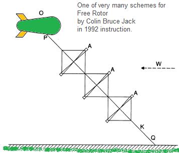
EXAMPLE 5
BEAN elements may be assembled into a 'STALK' composed of any number of BEANs
(including one) as illustrated in Figure 5. The upper end of the STALK may be
supported by a tethered balloon O. (This may have a streamlined airship-like
shape as shown to nunimize the wind drag on it). The central cable K may be
made of a material having very high strength-to-weight ratio such as Kevlar.
The secondary cables L, M may be made of conducting material (e.g. Dural) as
in Example 4.
The whole structure is constrained to rotate as a unit (e.g. by varying the
drag force on the sets of secondary propellors B in an appropriate way) so
that the central cable does not become twisted. The only rotating joints
required are at tiie top of the structure P, where it attaches to the
airship, and the base Q, where it attaches to the ground. The rotation at
these points may be forced (e.g. using small electric motors) to ensure no
twisting occurs at these points.
While in the air, the structure can be actively controlled. The force on any
rotor blade may be varied by the methods described in Examples 3 and 4.
Active control can achieve the following benefits among others:
(a) The STALK can be forced to a specific, optimal, elevation angle.
(b) Catenary hanging of the STALK may be m __nized, to keep it straight.
SUBSTITUTE SHEET
(c) The STALK can be forced to a given angle with respect to the incident
wind direction.
(d) Large scale oscillations in the STALK can be damped or prevented from
starting.
(e) The STALK may be bent along its length to allow for variations in wind
speed and direction with altitude.
Note that by using tiie secondary propellors B, the structure may also be
controlled when it is stationary-. The secondaries can be made to induce drag
(simultaneously generating a small amount of power, if desired), or driven
(e.g. by electric power supplied from the ground) to produce thrust This is
relevant to the starting and stopping of the rotation of the structure, to
preventing rotation during deployment and recovery, and to providing lift and
guidance forces during deployment and recovery.
Individual rotors may be equipped with tiieir own sensors for monitoring
position, orientation, incident wind, etc.
Note that all cables are in place tiiroughout deployment, so power and
control can be provided from the ground at all stages in deployment and
recovery without interruption. Some fully insulated conducting cables may be
incorporated (of relatively low power-carrying capacity) to allow power to be
supplied without involuntary cross- connexions or earthing occuriαg during
these operations.
The structure is deployed and recovered as follows. Initially the rotors rest
on tiie ground adjacent to one another (or stacked). The cables connecting
them are already fastened in place, but are slack. Consider tiie nodes to be
labelled 1 (the node immediately below the balloon), 2 (the node below tiie
uppermost rotor), 3 (the node below the second uppermost rotor), and so on in
sequence.
The balloon might simply be released, allowing the structure to self-deploy
with each rotor pulling the next into the air as it rises. For more
controlled deploment, however, two sets of winches are used, designated S and
T. Initially winch set S are connected to node 1 and are taut and set T to
node 2 and are slack. The set S are wound out until the balloon has lifted
the first rotor into the air, set T become taut and set S slack. Now set S
are disconnected from node 1 and connected to node 3. Set T are wound out
until the second rotor is in the air and set S are taut; set T are
disconnected and connected to node 4; and so forth.
To recover the STALK the operation is simply reversed. To do this it is
necessary to attach winch cables to nodes which are one rotor height above
the ground: a light crane with an appropriate instrument attached to its jib
may be used to do this. Gas may be released from the balloon as the structure
is hauled in, minimizing tension in the winches.
Note that there is no requirement for any cable which is part of the
permanent structure (either the Dural conductors or the central Kevlar
tether) to be wound on a winch under tension, either during deployment or
recovery.
The STALK may be kept operating even if individual parts fail. For example if
the bearings of a secondary propellor or its attached generator fail, the
pitch of the blades of the stationary propellor may still be altered to
produce the drag force required. If even the pitch control mechanisms fail,
other secondary propellors on the other blade tips of the affected rotor may
be used to control its motion so that it does not spin out of control. _
EXAMPLE 6
This example describes an alternative form of STALK illustrated in Figure 6.
In this form, rotors are cross- connected by wires such as R (rather than
being seperated by nodes) so that the whole structure becomes rigid under
tension. An advantage is that the string can be controlled using just one or
a few rotors (e.g. the topmost one) which are equipped with the control
mechanisms described in Example 4.
EXAMPLE 7
This example lists alternative upper suuports for the stalk. These include:
(a) The supporting balloon may be equipped with small electric motors and/or
rudder and fins, to allow it to manouvre. This may be useful to hold the
STALK at a desired angle, e.g. to optimize performance or prevent it becoming
twisted or entangled with neighbouring STALKs in exceptional weather
conditions such as flat calm or high relative turbulence. A manouverable
balloon may also assist during deployment and recovery, by pulling the upper
end of the STALK to a desired position and holding it there.
(b) The supporting balloon may be a circularly symmetric shape (e.g. a
flattened disk) so that it can rotate freely. This removes the need for an
upper rotating join. Rotation might be assisted by small tangential
propellors, to prevent twisting.
(c) A self-propelled airship. The STALK hangs below the airship, either with
all rotors aboard, or strapped just below the ship, or already deployed as a
string. The airship travels to the point where the STALK is to be moored.
This might be e.g. a buoy or disused oil platform at sea. The STALK is
moored, and power generation starts.
(d) A conventional heUcopter. After deployment and rotation is initiated, the
STALK becomes self-supporting due to the autogyro effect, and the helicopter
can detach and return to base.
(e) The topmost element of the STALK is a heUcopter with electrically driven
blades (power is provided along the STALK). After deployment, the angle of
the blades is altered and the heUcopter becomes an additional
power-generating autogyro.
(f) A disposable balloon which is jettisoned upwards after deployment is
complete.
(g) The rotor or rotors might take themselves take the form of lightweight
structures (rigid or inflatable) filled with a light gas or with hot air
(waste heat from the generators), so that each can support its own weight by
static lift
(h) The secondary propellors B can be swiveUed so as to provide directed
thrust, drive power being suppUed
SUBSTITUTE SHEET
f_om tiie ground. The propellors B can be used to provide lift, so that each
rotor can rise from the ground under its own thrust lift may similarly be
provided by seperate vertical-axis propellors mounted on any rotor, or the
topmost one, e.g. at the centre of the rotor. (0 The primary propellors may
be spun on a ground based turntable or turntables so that they can take off
and/or land using tiieir own lift force. .
(j) Parachutes may be deployed from any rotor, or the topmost one, to assist
in recovery, (k) Jet engines or solid-propellant rockets may lift the rotors.
(D Forced airflow provided by propellors or jet turbines on the ground may be
used to lift the rotors, (m) The rotors may be flown off or landed like a
kite, lifting in the wind without rotating by angling the blades
appropriately. During operation, supplementary lift may be provided by wing
structures attached to the central tether K and/or designing the upper
balloon to have a lifting-body shape. In tiie absence of wind, power suppUed
from tiie ground to the secondary propellors may be used to keep the
structure rotating and hence generate lift
EXAMPLE 8
This example describes alternative sites to which the STALK may be deployed.
In each case, the STALK may be recovered by the same means by which it is
deployed. In each case, each single set of deployment equipment and storage
and servicing faciUties can supply many STALKs to different sites.
(a) The STALK may be attached to a buoy or moored vessel at sea. An undersea
cable to land transmits the power generated. The STALK may reach this site
by:
(1) Being deployed from an appropriately equipped vessel, e.g. an oceangoing
barge, at the site.
(2) Being transported and deployed from an airship as described in Example
7(b).
(3) Being deployed as described in Example 5, from a site which is adjacent
to a seaport After deployment, the anchoring end of the STALK is transferred
to an oceangoing tug, which proceeds to tow the airborne STALK to site. The
tug either moors there for the duration, or transfers the anchoring end of
the STALK to a buoy.
(b) The STALK may be attached to an unmoored sea vessel, either drifting or
proceeding under power. The electricity produced might be used to generate a
storable fuel, such as hydrogen electrolyzed from sea-water. The vessel may
foUow a course so as to maximize the wind energy accessible, e.g. by
remaining under one of the major jetstreams.
(c) The STALK may be attached to a point on land other than than at which it
is initially deployed, either:
(1) Being transported and deployed from an airship as described in Example
7(b).
(2) Being transported from one site adjacent to the sea or a canal to another
(e.g. from a port to a set of coastal or offshore island sites) by oceangoing
tug or similar vessel as described in Example 8(a)(3).
(3) Being transported from the site of original deployment to another site by
being moored to a mobile land vehicle, e.g.:
(a) A heavy tracked vehicle.
(b) A railway vehicle, which might run on more than one set of parallel
tracks. In use, the anchoring end of the STALK might be kept on board the
vehicle (which could be secured to the spot by ties), or transferred to a
separate ground anchorage point The STALK might be deployed to a hill or
mountain top to minimize tether length and/or maximize wind speed past the
rotors.
. EXAMPLE 9
This Exanφle lists alternative forms which the main rotors might take:
(a) Biplane structure.
(b) Triplane, quadriplane, etc., structure.
(c) Inflatable structure.
(d) Tensile structure held deployed by centrifugal force.
(e) Tensile structure held deployed by aerodynamic forces.
(f) Thin-walled structure held rigid by internal pressure.
Note that although the primaries are depicted in the Figures as having two
blades each, both the primary and secondary rotors may have an unrestricted
number of blades. There may be any number of secondary blades (from zero to
several) on each primary blade tip.
As weU as being equipped with flaps (and/or other aerodynamic surfaces) the
geometry of the rotors may be alterable in other ways. For instance rotating
collars at the central join may permit the pitch of the blades to be altered.
The length and or anchorage points of the tethering lines C and E may be
capable of variation (e.g. by winches, hydrauUc pistons, etc.) so as to warp
the rotor, or move one part relative to another, or vary cycUcaUy in such a
way that the plane of rotation of the rotor Ues other than normal to the
central tension cable.
The rotors may be attached to the central cable only at the midpoint (with no
auxiliary supporting lines C, E to other points as shown in Figures 3) if
they are sufficiently strong. For example a biplane rotor could be of this
type. In this circumstance, appropriate moving joints (e.g. a universal
joint) might permit the rotor to turn in a plane other than normal to the
central tension cable. The joints might be motor driven so that the rotor
could be forced to a chosen angle with respect to the central cable.
The blades of the rotor need not necessarily Ue in the same plane, e.g. they
might form a shallow cone. The dihedral angle may be adjustable. For exanφle
once the blades are spinning the central joint may hinge freely so that the
blades adopt an equilibrium angle determined by the ratio of centrifugal
force to axial drag force.
The rotor blades may be deployed only once aloft, e.g. if they are tensile or
inflatable structures.
SUBSTITUTE SHEET
The rotor blades may be capable of extended deployment once the rotor is in
die air and rotating, e.g. by the blades extruding telescoping sections, or
by allowing the central structure to extend so increasing the overall
diameter of the rotor. The lengths of the bracing wires L, M may be
adjustable.
The rotor blades may be de-iced by circulating waste heat from the generators
along them (e.g. in tiie form of hot air) or by electric heating elements.
The directions of rotation of the secondary propellors mounted on a given
rotor may be chosen so as to minimize gyroscopic forces as tiie rotor turns.
Rotors may be mounted on a non-rotating cable by means of a bearing
permitting rotation. Consecutive sections of the main cable may rotate in
different directions or at different speeds if they are joined at a collar or
bearing permitting rotation. In either of these cases, individual rotors may
turn each at an independent speed and in either a clockwise or anticlockwise
direction.
EXAMPLE 10
This Example lists alternative ways in which energy may be generated by the
system once airborne. Note that once tiie system is deployed, it can support
a larger weight than could be held up by the top balloon alone due to the
autogyro lift effect Thus for example a Ughtweight pipe can be filled with
water once the structure is spinning without causing it to descend.
(a) Rotor blades may be lofted into a Jetstream.
(b) The rotor-tip energy harvesting devices may be other than propellors,
e.g. enclosed turbines, turboprops, etc.
(c) Pairs of counter-rotating rotors may generate energy directly from the
torque force between them, without the need for rotor-tip energy harvesting
devices.
(d) The temperature difference between air at low level and air at high
altitude may be used to generate energy, e.g. by using a working fluid which
rises up the structure as a vapour, condenses at the top and flows back to
the base, or theπnoelectrically. The rapidly turning rotors will serve as
efficient heat exchangers.
(e) Water may be pumped up the structure, flow out to the tips of the rotor
blades and be expelled rearwards relative to the direction of turn. The water
may pass through turbines en route so generating energy.
(f) The difference in electric potential between air at high and low
altitudes may generate a current flow. This may be maximized by mati g the
airflow over the rotor blades turbulent; by dissipating water vapour to
increase the conductivity of tiie surrounding air; or by using trailing or
fixed wires, meshes or cages attached to parts of the structure, including on
the rotor blades.
EXAMPLE 11
This Example describes how mechanisms described in this patent may be used
for purposes of weather or climate or
other environment control:
(a) By choosing at what times, places, and altitudes to extract energy from
the wind and thus slow the local airflow. Place of extraction may be selected
by drawing power from a selected subset only of an extended network of STALKs,
or by the STALKS themselves being mobile (e.g. as the ship-mounted variety
described in Example 8(b)). .
(b) By deploying the rotors so as to alter tiie direction of the surrounding
airflow.
(c) By deploying the rotors so as to suck cold air down from high altitude to
low altitude, or lift warm air from low altitude to high altitude, etc. Note
that a 'cascade' or 'staircase' effect can be set up to pass the same air
from one rotor to the next
(d) By deploying the rotors to increase the turbulence of the surrounding
airflow. For example, causing a localised Jetstream to exchange momentum and
material with the surrounding air.
(e) By supplying power from the ground to the rotors, so setting static air
in motion, or accelerating the surrounding air; in particular to trigger a
self-sustaining process, such as allowing an unstable system of cold air over
warm air to right itself.
(f) By pumping water up tiie structure to be sprayed out at altitude.
(g) By dispersing 'seeding' material (encouraging the formation of ice
crystals or water droplets) from the structure.
(h) By dispersing soot particles or other sunUght-absorbing particles from
the structure.
(i) By dispersing any kind of material from the structure.
(j) By deploying the rotors so as to suck polluted air from low altitude to
higher altitude, or suck fresh air down from high altitude to low altitude.
Other structures than the rotors might be deployed from the structure to
assist weather control functions by interacting with the airstream, e.g.
braking parachutes, paragliders, etc.
Note that the 'butterfly effect' can be employed to enable a small initial
alteration to lead to a much larger subsequent change in the weather pattern,
including at points remote from the STALK system(s).
'Weather control' can of course include the dispersal of low-lying smog,
cloud or fog. In particular note the possibility of dispersing smog from
areas such as tiie Los Angeles basin by injecting clean air from higher
altitudes using a BEANSTALK or cascade thereof.
EXAMPLE 12
This exanφle describes in more detail how electric power may be conveyed from
the generating sites on the STALK to the ground.
(a) Tngιιlnt_v* conducting members may be cooled by allowing cold air to pass
along a passage within them. The airflow may be created by passive means,
e.g. using tiie fact that hot air rises; using the dynamic pressure of tiie
wind; using the dynamic pressures created by the turning of the rotors (e.g.
by having air enter and
SUBSTITUTE SHEET
leave from slots or scoops situated on the rotor wings); and/or using the
Venturi or Bernoulli effects. Air may enter and leave such a system at many
points along its height
(b) The transmission voltage may be raised well beyond tiie insulation limits
of individual generators if a chain of generators are connected in series.
Since generators are effectively isolated from the ground as weU as from one
another, a high potential difference between generators, or between a the
generator casing and the earth, does not matter.
(c) Power may be generated at different frequency from that required (e.g. as
DC to minimize the weight of tiie conductors carrying tiie current to the
ground, or at high frequency to minimize the mass of the generators), being
transformed to mains frequency by apparatus on tiie ground.
(d) lightning strikes may be protected against either by arranging for
circuit breakers, isolators etc. situated anywhere on the structure (on tiie
rotors or on the cables) to effectively insert a large thickness of ■nmilating
material between individual rotor blade tips, between separate rotors, and or
between ti e rotors and tiie ground below; or by arranging for all of tiie
conductors to be cross-connected so that all cables which normally transmit
power from the rotors to the ground act as a combined Ughtαing conductor of
high capacity.
EXAMPLE 13
An apparatus identical or very similar to that described in each above
Example may be deployed in water, as distinct from in air, to harvest energy
from the flow of water in tiie form of an ocean current, a tidal flow, or a
river current The structure may be given an overall negative buoyancy,
positive buoyancy, or neutral buoyancy. The anchorage point of the tether may
be to a fixed structure situated on the sea bed below; or to a fixed
structure situated on land above; or to a fixed intermediate point (such as
the peak of a submarine mountain); or to eitiier a mobile structure or a
second rotor system which may be eitiier floating or airborne and is immersed
in a medium flowing at a different speed and/or in a different direction to
the current surrounding tiie rotors.
As a specific example, a STALK of rotors each having a stight positive
buoyancy is tethered to a point on the seabed beneath a permanent ocean
current Such currents have speed — 10 times less than wind speeds: however
sea-water is 1000 times denser than air, so the density of kinetic energy
available per unit area is similar to that for an airborne structure. Current
may be transmitted from the STALK base to land via an urdersea cable. The
salt-water in which the system is immersed may be used as a current conductor
(e.g. for one phase of an alternating current produced).
Of particular importance is the effect such a structure could have on
weather/climate/environment control. Where tiie rotors are in sea water whose
temperature differs from that of its surroundings (e.g. in a warm current
such as tiie Gulf Stream, or due to tiie temperature difference between the
sea surface and the depths) the relative thermal energy in each tonne of
sea-water may be 4 to 5 orders of magnitude greater than ti e kinetic energy.
UTE SHE T
Thus extracting a small amount of kinetic energy can be used to cause major
environmental effects, by slowing or diverting a sea current, or by
transporting water between different depth layers in the ocean. Setting up
turbulence in the current flow may enable ocean silt (carrying plankton
nutrients) to be stirred up from the sea bed and distributed. The melting or
formation of ice and the subsequent flow of the water and/or icebergs
produced may also be controlled. .
EXAMPLE 14
This Example describes in more detail how the STALK described in Example 5
may be deployed and recovered.
The balloon supporting the top of tiie STALK is an an unmanned airship
equipped with electric motors (powered from the ground via the STALK) which
are capable of propelling it in any lateral direction. If the airship has
circular symmetry (e.g. disk shaped) this may be accomplished without
changing orientation. (The motors may also be capable of propelling it in the
vertical direction.)
The airship may use a Ughter than air gas such as hydrogen, helium or
methane, to provide lift; or hot air; or steam; or a combination (to permit
both high lift and controllability). Note that power (e.g. to heat hot air)
may be provided via the STALK; also, via a suitable pipeline on the STALK,
tiquids or gases (water, hydrogen, etc.).
Th~ lift force from the airship may be varied by taking on board or expelling
overboard ballast (e.g. water) anα or by taking on board or expelling
overboard gas (e.g. hydrogen, hot air, steam) and or by condensing steam to
water or vice versa and/or by its motors.
Initially the BEAN rotors Ue on the ground with the STALK cables already
connected. The airship rises from the ground with enough lift to support its
own weight. As it rises lift force is increased (e.g. by dumping ballast) so
that it can lift an increasing number of BEANs suspended below.
As the cable(s) between the airship and the first BEAN become taut the first
BEAN is jerked into the air. (Ascent speed might be ~2 metres/sec.) Shock
absorbers between the BEAN rotor and the central STALK connexion and/or on
any secondary cables supporting the outer parts of the rotor protect the BEAN
from damage. The ascent continues until the second BEAN is lifted into the
air also, and so forth.
During deployment the airship's motors keep it in the correct relative
position to the BEANs on the ground below. Moreover, the secondary propeUors
on the airborne BEANs may be energized (using power from the ground) to
maintain the BEANs in a precisely vertical line, and prevent them from
twisting with respect to one another. In particular, the BEAN which has most
recently left the ground is moved accurately into position with respect to
the one it is about to puU aloft So the whole airborne structure is precisely
controlled throughout deployment.
SUBSTITUTE SHEET
Note that since any electric generator is also a motor, the generators to
which the secondary propeUors are attached can also be used to drive them, by
providing electric power.
If the secondary propeUors are insufficient for lateral flight control (for
instance in the case of twin-bladed primary rotors, whose secondaries can
provide thrust in only one direction relative to the rotor) then the, primary
rotors may have additional propeUors whose function is to provide thrust in
other directions.
Once the whole STALK is airborn and vertical, the STALK is allowed to drift
sideways in tiie wind towards its operational lean angle, and rotation is
started.
The BEANSTALK is recovered by a similar procedure. The secondary propeUors
are used to halt the rotation, and then, they and the airship's propeUors are
used to return the structure to a vertical position above the landing site.
lift from the airship is then steadily decreased (e.g. by venting lifting
gas, or allowing hot air to cool, or by pimping ballast water up the STALK),
so that the structure descends at a steady rate. As each rotor hits the
ground, the shock is absorbed by undercarriage structures (e.g. skids or
wheels) at the tips and/or centre of each rotor.
As during ascent, precise position control of the airborne part of tiie
structure is achieved using the propeUors on both the airship and the rotors.
Thus each rotor is landed in the correct position with respect to those
already on the ground (e.g. adjacent to but not on top of the preceding
rotor). The connecting STALK cables may also be deposited on the ground in
any desired pattern, e.g. a zigzag which does not cross itself or the rotors,
or a loose pile or coil, in which they occupy minimum ground space. Lastly,
the airship itself is recovered.
The STALK may be transported to another site than its launch one. After
initial vertical deployment, the STALK may be detatched from the ground,
allowing the airship to proceed under its own power (e.g. petrol engines) to
the destination site, to which the base of the STALK is secured.
Alternatively, the base of the STALK may be fixed to a surface vehicle (e.g.
an oceangoing tug). This vehicle may provide electric power to the STALK to
drive along the airship and rotors (preventing any excessive forces in the
STALK cable, or twisting, etc. from occurring) so that the vehicle and
BEANSTALK proceed together to the deployment site. The base of the STALK is
then connected to the deployment site (e.g., transferred from an oceangoing
tug to a mooring buoy).
EXAMPLE 15
This Example lists miscellaneous additional features and options.
The structure may take off/land with the help of streams of air provided by
fans or jet tiuusters on the ground. The structure may take off/land with the
help of ground effects a la hovercraft.
The structure may take off/land with the help of magnetic levitation.
Possible flight modes include one in which the main rotor blades provide lift
force without rotating, i.e. like a kite.
Individual rotor blades may connect to the central STALK by tensile wires
only (held taut by centrifugal force during operation). Such blades may be
equipped with control surfaces allowing them to take off and land
horizontally like an aircraft (individually or together). In the latter case,
a circular runway with a rotating central structure may constitute the ground
base. The runway may be conventional, or take the form of a circular canal,
lake, railway track, or maglev track.
Individual blades may be capable of separating and/or joining to the STALK in
mid-air, taking off and landing separately for maintenance while the STALK
continues to function.
A rotor may rise from the ground under its own lift either using its
secondary propeUors to provide helicopter¬ like vertical takeoff; or
accelerating the primary horzontally until it generates lift like an aircraft
wing for horizontal takeoff; or by tilting a non-rotating primary so that it
lifts in the wind like a kite; or by spinning the primary so that it itself
generates a heUcopter type lift; or by spinning the primary tilted with
respect to tiie prevailing wind so that it provides autogyro-type lift (the
secondaries may provide any necessary lateral force(s) in each case.) These
flight modes may also be used in circumstances (such as in light winds) where
the rotors must be kept aloft, but not generate power or cause high tensile
forces in the STALK tether.
The main rotors may have an upwardly arched form so that in wind die tips are
puUed apart from one another, preventing a compressive force in the rotor
arising due to the tension in the secondary tethers.
The blades of each main rotor may be connected by wires running approximately
circumferential to the rotor (from blade tip to blade tip, and or
intermediate points on each blade), for additional strength and rigidity.
The secondary propeUors may themselves be equipped with tertiary propeUors
(and so on) for power extraction; e.g. to provide power at the highest
possible revs.
The structure may take off or land from water (e.g. the sea surface).
Parachutes may assist an unpowered 'splashdown'.
The BEANSTALK structure may weU make use of active control systems to guide
it during deployment, recovery, and power-generating operation. These systems
may use sensors to detect relevant parameters (e.g. rotor position and
orientation, wind speed, etc.), situated on the ground below and/or on any
parti's) of the structure, including on each rotor blade and also on the
airship. Control may be provided by a single computer (e.g. on the ground
SUBSTITUTE SHEET
below or on the airship), or micro-processors situated on each rotor (which
may have faciUties for communicating with one another and/or with a main
controlling computer) or any combination or multiplication of such systems.
Individual rotors and or the system as a whole may be intrinsically unstable,
stability being provided by the active control system(s).
The rotating STALK tether may be clad in counter-rotating ailerons to
minimize the wind force on it The STALK may have an upper rotating part
(including the rotors) joined at a rotating collar to a lower part which does
not rotate. This lower part may be given an aerodynamicaUy shaped
cross-section, to minimize wind force on it In eitiier case some controllable
ailerons may be provided so that the movements of tiie STALK tether itself
may be actively controUed.
The rotor blades may be hinged so that during deployment they hang parallel
to the STALK and swivel outward under centrifugal force when rotation is
initiated. In this case tiie blades may be all-tensile and very numerous
(e.g. strips of shaped plastic deploying into a Maypole-like structure). The
strips may be each of slightly different length so that the secondary
propeUors at their tips do not collide with one another during deployment The
strips may be controUed by twisting them at either end. The ends of the
hinged blades (and/or intermediate points on the blades) may be connected by
tensile wires so that the blades are forced into a rigid cone under
centrifugal force.
A BEAN rotor may be deployed in the sky as an all-tensile structure which is
initiaUy folded (e.g. as a slotted parachute which bells out and starts
rotating under wind force).
The secondary propeUors may be attached to the rotor tips, or any other part
of the rotors, or deployed from the rotors (e.g. on tensile tethers deployed
further outward by centrifugal force).
The system of using secondary propeUors to extract energy from a main rotor
at higher revs/lower torque than could be done directly can be appUed to an
otherwise conventional ground-based rotor of any type. This includes
horizontal-axis turbines and also vertical-axis designs such as the Darrieus.
The secondary propeUors may have the effect of diminishing the vorticity
introduced into the airstream due to the rotation of the primary. This may
increase the efficiency of the system and also cut down interactions between
neighbouring turbines on the same STALK, and between adjacent STALKs.
A single airship may support more than one STALK, or be fastened to the
ground by conventional tether(s) as weU as by energy-generating STALK(s),
particularly to aid deployment and recovery.
A single STALK may be supported by more than one airship.
SUBSTITUTE SHEET
An airship connected to the ground by conventional tether may deploy a
free-hanging STALK of rotors. The rotors, tending to trail behind the
airship, may be flown up to an altitude above the airship itself, e.g. to
intercept higher wind speeds.
Where the secondary propeUors are used to provide lift during deployment and
or recovery of the system, the secondaries may be turned into the verical
plane eitiier simply by turning the whole rotor into this plane (especially
in the case of a two-bladed rotor) or by swivelling the mounts on which the
secondaries are mounted or by swivelling the end parts of the primary rotors.
Single-rotor systems can include a very large rotor (up to — 1 km radius).
The rotor might take the form of an airship, or a structure which is unfolded
or inflated or deployed by centrifugal force from the airship, which may
itself spin with the rotor.
The speed at which the secondary propeUors turn may be controUed by varying
the resistivity (inductance, resistance, capacitance, reactance etc.) of tiie
circuits to which they are connected, especially if they are of fixed-pitch
design.
Consecutive rotors of the STALK may be directly connected by wires which
physically prevent them becoming twisted with respect to one another.
A set of rotor blades which do not aU lie in the same plane may be
cross-connected into a cylindrical structure having effective
three-dimensional rigidity.
Emergency recovery procedures may incude separating the rotors forming a
BEANSTALK from one another by means of explosive bolts, and deploying
parachutes from each rotor tip (or rotor centre) to slow their fall. If the
airship and STALK escape from their ground anchorage, the airship envelope
may be opened by remote control to cause the system to fall into the sea or
onto uninhabited land.
If the airship at the top of the STALK suffers catastrophic failure, a
parachute may be deployed at this point to allow non-destructive recovery of
the rotors.
Cross-wires which support the rotor blades (for example cross-wires from a
node below which support the rotor against aerodynamic force) may attach to
the central STALK cable or to a rigid vertical spar forming part of the
rotor.
Cross-wires may repeatedly bifurcate as they run from the node to their
anchorage points on the rotor. Since aerodynamic forces are ~ 10 times
greater than gravity forces on each rotor, each rotor might have supporting
cross-wires to a node below but not to a node above. Of course not all
cross-wires from a given rotor need
SUBSTITUTE SHEET
terminate at the same node, and there may be a gap between the point where
cross-wires running upward from one rotor meet tiie central STALK support and
that at which the cross-wires running downward from the next rotor above meet
the central STALK support
The secondary propeUors may be oriented in another direction than facing the
local airflow (i.e. approximately tangential to the main rotor). In which
case, aerodynamic surfaces may be employed which divert tiie direction of
tiie local airflow to drive ti e secondaries effectively.
De-icing of the rotor blades may be effected by electric heating or by
circulation of coolant (e.g. heated air) warmed by the electric generators.
This heated coolant may also be used to provide buoyancy, e.g. pumped to a
hot-air airship supporting the BEANSTALK.
Attitude sensors aboard the rotors may include fibre-optic gyros. Position
sensors may make use of a radar system very similar to the precision landing
guidance systems used at many airfields.
Note that two-bladed main rotors occupy little ground area compered to rotors
with 3 or more blades, and so may be landed side by side. Very large 2-bladed
rotors may be transported on a long narrow vessel such as an oceangoing
barge.
In order to minimize the size of the secondary propeUors, while also allowing
the secondaries to rotate with a tip speed below the speed of sound, the
primary rotors may be twin bladed with high tip speed to airspeed ratio and
the secondaries multi-bladed with low tip speed to airspeed ratio.
An alternative method of STALK deployment: The airship may be launched to
altitude while the rotors remain on the ground below. The rotors then climb
the airship tether cable using wheeled attachments which grip it. The rotors
ascend in procession with the main tether (incorprating high strength and
current carrying capacity) shing between them, until the main tether becomes
taut.
An airship at the STALK top may be supplied via a STALK pipeline with
materials including liquids which are then heated to become lifting gas, e.g.
water to steam, liquid methane to gaseous, etc. Control of the lift force of
the airship may also involve cooling lifting gas to liquefy: steam to water,
gaseous to liquid methane, etc. The STALK pipeline may supply combustible
fuel (liquid or gas), as weU as electricity, to power the airship and provide
any auxiliary power or heating required on the rotors or the STALK itself
(e.g. to prevent icing).
If the airship supporting the BEANSTALK has circular symmetry, the top rotor
may be connected to it with tethers connecting the outer parts of the rotor
to the outer parts of the airship, so that the airship is constrained to
rotate with the BEANSTALK without the uppermost part of the cable becoming
twisted. Alternatively, the circular airship may be equipped with propeUors
which force it to rotate at the same speed as the STALK.
SUBST
Note that all primary rotors are normally constrained to rotate at the same
rate (and sometimes constrained not to rotate at aU) so no part of the STALK
becomes twisted. This is normally done by varying the speed and/or pitch of
the secondary propeUors, altering the drag force (sometimes the thrust force)
which they exert on the rotor tips, and tiie amount of power drawn from (and
sometimes supplied to) each set of secondaries.
If the airship does not have circular symmetry, so that it must face into the
wind during BEANSTALK deployment and recovery, then the secondary propeUors
on the rotors may be used to twist the lowest rotor to a different angle to
that it would normally make with the airship above during recovery, so it may
be landed with any desired orientation (e.g. parked parallel to the rotors
already on the ground) irrespective of changes in the airship's orientation.
During recovery, the secondary propeUors on a rotor may be brought to a halt
just before the rotor is landed, and turned to such a position that the tips
of the secondaries avoid hitting the ground (e.g. parallel to the ground in
the case of twin-bladed secondaries).
The secondaries may be used to force-start the initial rotation of the STALK
(e.g. foUowing initial deployment). To do this, power is supplied to the
generators to which the secondaries are attached, so that they act as motors
and drive the secondaries, as described above.
Note that a disk-shaped airship combines the properties of rotational
symmetry (so it may turn with the STALK), minimal wind drag, and the ability
to act as a lifting-body aircraft when tilted with respect to the wind. In
wind, the tension of the STALK wiU tend automatically to tilt it in an
appropriate way to accomplish this.
EXAMPLE 16
A STALK may support turbine(s) of the Darrieus type in any of the foUowing
ways. In each case, the turbine blades may be all-tensile structures deployed
by centrifugal force:
(a) The STALK may form a single turning Darrieus blade as in Figure 7(a).
(b) The STALK may form a zigzag of single Darrieus blades as in Figure 7(b).
(c) The STALK may be constitute the central column of one or more Darrieus
turbines each having two or more blades as in Figure 7(c).
(d) The STALK may bifurcate (or trifurcate etc.) into one or more Darrieus
turbines each having two or more blades and no central column as in Figure
7(d).
In each Figure 7(a)-(d) O denotes the supporting airship, S a Darrieus
turbine blade, and T a secondary energy- generating propeUor. The wind
direction is into the paper.
Note that as weU as a STALK of Darrieus turbines connecting to the ground,
such a STALK may be deployed free-
SUBSTITUTE SHEET
hanging from an airship. An end weight or aerodynamic device such as a
propeUor or drogue parachute may help maintain tension in tiie tether.
Force on the Darrieus blades may be varied, by means of control surfaces or
by twisting the blades or by manipulating the secondary propeUors, e.g. to
control' the orientation of the turbines and/or to control the direction and
magnitude of tiie wind force on them (e.g. to provide a lift force).
The secondary propeUors may be situated at a slightly different point on each
blade making up a Darrieus turbine as in Figure 7(e), so that they do not
collide during deployment
EXAMPLE 17
This Example describes in detail a largely tensile implementation of the
design. It is illustrated with respect to Figures 8a-g. Figure 8a shows a
'front' view during initial deployment; Figure 8b a 'side' view during
rotation initiation (one rotor blade only visible); Figures 8c-f side views
during operation; and Figure 8g a reinforcing boom.
A spherical balloon A supports via tensile cables B two or more primary rotor
blades C (which may be tensile or semi-rigid or rigid structures) which at
their ends support assembUes which comprise secondary rotors D attached to
electric motor/generators E (there may be just one secondary rotor per
assembly, or an array containing a large number of small secondary propeUors
each with its own attached motor/generator) and also aerodynamic surfaces F
used for control purposes as described below.
Initially the balloon A rises into the air with the cables B and their
attached blades C banging approximately vertical and supporting the assembUes
D E/F. The balloon A may be capable of powered lateral motion (including
during the ascent) either by using electric power to drive the secondary
propeUors at the rotor ends, or by separate motors G mounted closer to the
central baUoon A (e.g. upon or beneath it).
Either the secondary propeUors D or the motors E are used to force the whole
structure to start rotating. As it spins faster, centrifugal force tends to
deploy the rotors and their end assembUes pointing outward from the central
balloon.
Once spinning, the aerodynamic surfaces F come into play. Each assembly F may
actually consist of a multipUcity of aerodynamic surfaces mounted in
different planes, and incorporating movable surfaces (e.g. like the tailplane
assembly of a conventional aircraft) or the whole assembly being twistable
with respect to the rotor wing. As tiie structure spins, the assembUes F are
manipulated so as to control the orbit of each primary rotor blade C and also
the angle of attack of its outer end with respect to to the incident airflow
(and so to some extent the angle of attack and/or degree of warping of t e
entire rotor blade). The motion of each assembly may be likened
to a familiar toy in which a model aircraft attached to a fixed tether
continuously orbits a central point, but with the motion during each orbit
controllable to a substantial extent.
The orbits are controUed so that a drag force is induced on the structure, so
forcing it to deploy downwind ultimately as shown in Figure 8c. This is the
normal generating position. ->
The tethers to the structure may take a variety of forms. Figure 8c depicts
the simplest: one tether to the centre of rotation. An alternative form
(Figure 8d) has twin tethers to each rotor blade tip (none to the central
balloon). Figure 8e shows a variant of this form; Figure 8f a variant in
which bifurcating tethers attach ultimately to many points along each main
rotor. Figures 8d - 8f could all be modified to include an additional tether
to the central baUoon. In general the advantage of tethers to points other
than ti e central balloon (despite the fact that they add to drag from rotor
turning) is that they decrease the centrifugal force required to deploy the
main rotor blades effectively, thus in particular increasing the maτiιmιm
size feasible.
The main bearing H permitting rotation of the whole system may be sited on
the ground below (or upon a sea buoy) as in Figure 8c or at the cable main
bifurcation point as in Figures 8d-8f or at any intermediate point (or points
if redundancy is desired, so the structure can continue functioning if a
main, bearing fails).
There are two distinct ways of recovering the system:
(1) Rotation is rapidly halted, the rotor blades being steered so that they
do not collide with each other or the tether cables and coining to rest
dangling vertically below the baUoon. The arresting might be accomplished by
braking or reversing the pitch or reversing the direction of rotation of the
secondary propeUors; or (in emergency) by drogue parachutes deployed from the
main rotor blade tips. The balloon might then be winched in; or the secondary
rotors or auxiliary motors E might be used to fly the baUoon back to tiie
launch field, depositing the main tether cable on the ground or into the sea
in so doing.
(2) The main rotor blades are controUed so as to drive the system upwards
while still rotating until the main tether is nearly vertical. Rotation can
then be halted with less danger of the main rotor blades colliding with each
other or the tether cables, and with less distance to drive the system
against the wind to reach a point above the ground tether site if this is the
intended landing site.
Notes:
(a) During launch, rotation may be initiated before the tether is fuUy
deployed. Similarly, the tether could be partly wound in before recovery
method (2) is initiated (if it is used). Thus the baUoon need not be capable
of carrying its payload to the altitude represented by the fuU tether length.
The net lift of the system may be varied (e.g. to assist during launch or
recovery) e.g. by releasing lift gas or ballast water from the ' "loon,
and/or by pumping lift gas or ballast water up the tether to the baUoon.
(b) The tether system (in particular that point below the main bearing H)
might be jettisoned and left on the ground (or floating in the sea) still
attached to the ground anchorage point or sea buoy while the
SUBSTITUTE SHEET
balloon/rotor system is removed elsewhere for maintenance or replaced by
another.
(c) Tether cables may be aerodynamiclly shaped to minimize wind resistance
due to incident wind and or main rotor rotation. During startup and slowdown
of rotation, tether cables wll tend to trail behind the rotors to which they
are attached: if the secondary propllors are mounted on the leading side of
each primary rotor blade, they will not tangle with the tethers. *
(d) If the system is moored to a buoy at sea (which could contain the main
bearing H) the buoy may be designed so that it can without harm be dragged
beneath the water or lifted out of the water by the tension of the main
tether during operation.
(e) The central baUoon may be reinforced by internal wires; in particular
connecting the various anchoring points of the main rotors, so that tiieir
centrifugal force does not add to the stress in the baUoon fabric.
(f) Various measures may be adopted to ensure that all points of the main
rotor blades can be inclined at the appropriate angle to the incident airflow
during operation. In particular the fabric may be reinforced at intervals
along tiie wingspan by structural members called booms (running forward to
aft, i.e. circumferential with respect to the centre of rotation) which can
hold the fabric in the desired cross- sectional profile shape. The angle of
inclination at each boom can also be controUed, eitiier
(i) By running each boom beyond the aft edge of the main rotor wing and
equipping the aft end with a 'tailplane' set at an appropriate angle; or
(ii) By having tethering cables running to both fore and aft ends of each
boom J, as in Figure 8g.
In either case, the angle of attack might be adjustable, e.g. by varying the
angle of inclination of the tailplane or the relative lengths of the fore and
aft cables, permitting accurate 'trimming* for different wind conditions and
or during each primary rotor orbit (g) It is possible to deploy a stack of
the structures described in this Example as a 'STALK', tethered to one
another, rotating synchronously, and using a common main bearing and ground
anchorage point (h) A variant of tiie design could be deployed underwater,
e.g. in an ocean current The central baUoon could be replaced by a small
buoy. If the object was to slow or divert the current rather than generate
power, the secondary rotors would be used only to initiate deployment:
dissipative structures such as rotortip
'spoilers' would dissipate the energy generated by rotation.
=======================================
26.11.1992 Initial Publication with ISR (A1 29/1992)
45 pages. PDF.
===================================
The way that the inventor's name listed in the WIPO patent document is
confusing to me:
JACK, Colin, Humphry, Bruce" [GB/GB]"
Notice, no e in the Humphry which might be a typo. Apparently there are two
persons or not? Why repeat GB. ??? Or is that a list of his pen names;
Only one address: 38A, South Parade, Oxford, OX2 7JN. Not sure about the O or
0 in the zip code.
=============
Oxford Mathematical Designs, name of his LLC after he used it for many years
without LLC.
FOR ORIGINAL PATENT PAGES AND IMAGES, go to Documents tab after first
visiting the following page:
================= |