1
Article Flow Energy for SGRE 122 11
Using of High Altitude Wind Energy*
Alexander Bolonkin
V.P. of Consulting and Research Co.,
1310 Avenue R, #6-F, Brooklyn, NY 11229, USA
Abstract
Ground based, wind energy extraction systems have reached their maximum capability. The
limitations of current designs are: wind instability, high cost of installations, and small power output of
a single unit. The wind energy industry needs of revolutionary ideas to increase the capabilities of
wind installations. This article suggests a revolutionary innovation which produces a dramatic increase
in power per unit and is independent of prevailing weather and at a lower cost per unit of energy
extracted. The main innovation consists of large free-flying air rotors positioned at high altitude for
power and air stream stability, and an energy cable transmission system between the air rotor and a
ground based electric generator. The air rotor system flies at high altitude up to 14 km. A stability and
control is provided and systems enable the changing of altitude.
This article includes six examples having a high unit power output (up to 100 MW). The proposed
examples provide the following main advantages: 1. Large power production capacity per unit - up to
5,000-10,000 times more than conventional ground-based rotor designs; 2. The rotor operates at high
altitude of 1-14 km, where the wind flow is strong and steady; 3. Installation cost per unit energy is
low. 4. The installation is environmentally friendly (no propeller noise).
---------------------
Key words: wind energy, cable energy transmission, utilization of wind energy at high altitude, air rotor,
windmills, Bolonkin.
* Presented in International Energy Conversion Engineering Conference at Providence., RI, Aug.16-19. 2004.
AIAA-2004-5705, AIAA-2004-5756, USA.
Nomenclature (in metric system)
A - front area of rotor [m2];
α = 0.1 - 0.25 exponent of wind coefficient. One depends from Earth’s surface roughness;
Aa - wing area is served by aileron for balance of rotor (propeller) torque moment [m2];
Aw - area of the support wing [m2];
C - retail price of 1 kWh [$];
c - production cost of 1 kWh [$];
CL - lift coefficient (maximum CL ≈ 2.5);
CD - drag coefficient;
ΔCL,a - difference of lift coefficient between left and right ailerons;
D - drag force [N];
Dr - drag of rotor [N];
E - annual energy produced by flow installation [J];
F - annual profit [$];
Ho = 10 m - standard altitude of ground wind installation [m];
H - altitude [m];
I - cost of Installation [$];
K1 - life time (years);
K2 - rotor lift coefficient (5-12 [kg/kW]);
L - length of cable [m];
Ly - lift force of wing [N];
M - annual maintenance [$];
2
N- power [W, joule/sec];
No - power at Ho ;
r - distance from center of wing to center of aileron [m];
R - radius of rotor (turbine)[m];
S - cross-section area of energy transmission cable [m2];
V - annual average wind speed [m/s];
Vo - wind speed at standard altitude 10 m [m/s](Vo= 6 m/s);
W - weight of installation (rotor + cables)[kg];
Wy - weight of cable [kg];
γ - specific density of cable [kg/m3];
η - efficiency coefficient;
θ - angle between main (transmission) cable and horizontal surface;
λ - ratio of blade tip speed to wind speed;
v - speed of transmission cable [m/s];
ρ - density of flow, ρ =1.225 kg/m3 for air at sea level altitude H = 0; ρ =0.736 at altitude H =5 km;
ρ =
0.413 at H =10 km;
σ - tensile stress of cable [N/m2].
Introduction
Wind is a clean and inexhaustible source of energy that has been used for many centuries to grind
grain, pump water, propel sailing ships, and perform other work [1]-[4].
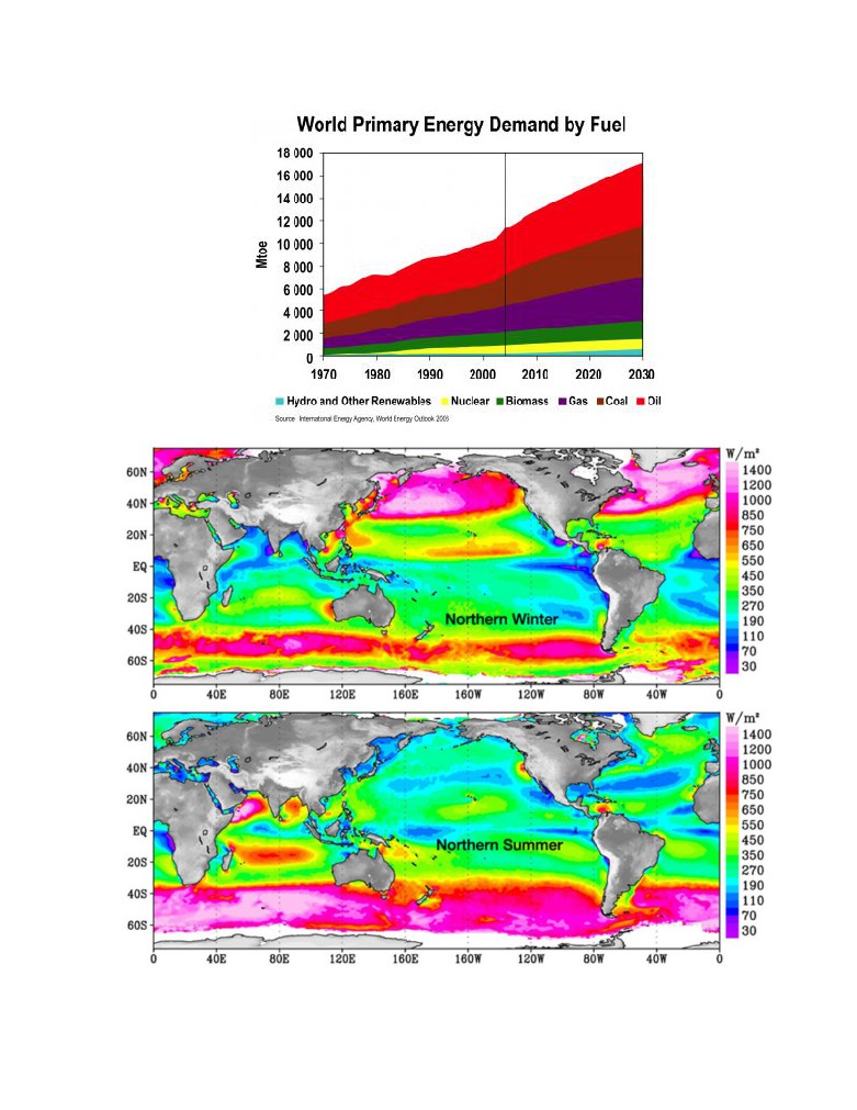
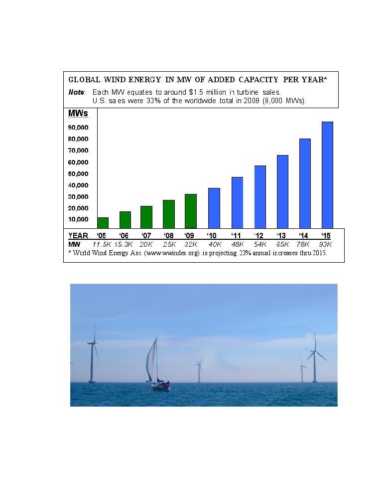
At the end of 2009, worldwide nameplate capacity of wind-powered generators was 159.2 gigawatts
(GW). Energy production was 340 TWh, which is about 2% of worldwide electricity usage; and has
doubled in the past three years (figs.1 - 2). Several countries have achieved relatively high levels of
wind power penetration, such as 20% of stationary electricity production in Denmark, 14% in Ireland
and Portugal, 11% in Spain, and 8% in Germany in 2009. As of May 2009, 80 countries around the
world are using wind power on a commercial basis (fig.3).
A program of the United States Department of Energy encouraged the development of new machines,
the construction of wind farms, and an evaluation of the economic effect of large-scale use of wind
power.
The utilization of renewable energy (‘green’ energy) is currently on the increase. For example, a lot
of wind turbines are being installed along the British coast. In addition, the British government has
plans to develop off-shore wind farms along their coast in an attempt to increase the use of renewable
energy sources. A total of $2.4 billion was injected into renewable energy projects over the last three
years in an attempt to meet the government's target of using renewable energy to generate 10% of the
country's energy needs by 2010 (fig.4).
This British program saves the emission of almost a millions tons of carbon dioxide. Denmark plans
to get about 30% of their energy from wind sources.
Unfortunately, current wind energy systems have deficiencies which limit their commercial
applications:
1. Wind energy is unevenly distributed and has relatively low energy density. Huge turbines cannot
be placed on the ground, many small turbines must be used instead. In California, there are
thousands of small wind turbines. However, while small turbines are relatively inefficient, very
huge turbines placed at ground are also inefficient due to the relatively low wind energy density
and their high cost. The current cost of wind energy is higher then energy of thermal power
stations.
2.
Wind power is a function of the cube of wind velocity. At surface level, wind has low speed and it
is non-steady. If wind velocity decreases in half, the wind power decreases by a factor of 8 times.
3
3. The productivity of a wind-power system depends heavily on the prevailing weather.
4. Wind turbines produce noise and visually detract from the landscape.
Fig. 1. World energy demand
Fig.2 Wind energy in World.
There are many research programs and proposals for the wind driven power generation systems,
however, all of them are ground or tower based. System proposed in this article is located at high
4
altitude (up to the stratosphere), where strong permanent and steady streams are located. The also
proposes a solution to the main technologist challenge of this system; the transfer of energy to the
ground via a mechanical transmission made from closed loop, modern composite fiber cable.
Fig.3. Global wind energy per year.
Fig.4. Current method for production wind energy - ground (sea) windmills.
The reader can find the information about this idea in [1], the wind energy in references [2]-[3], a
detailed description of the innovation in [4]-[5], and new material used in the proposed innovation in
[6]-[9]. The application of this innovation and energy transfer concept to other fields can be found in
[10]-[13].
5
Innovations
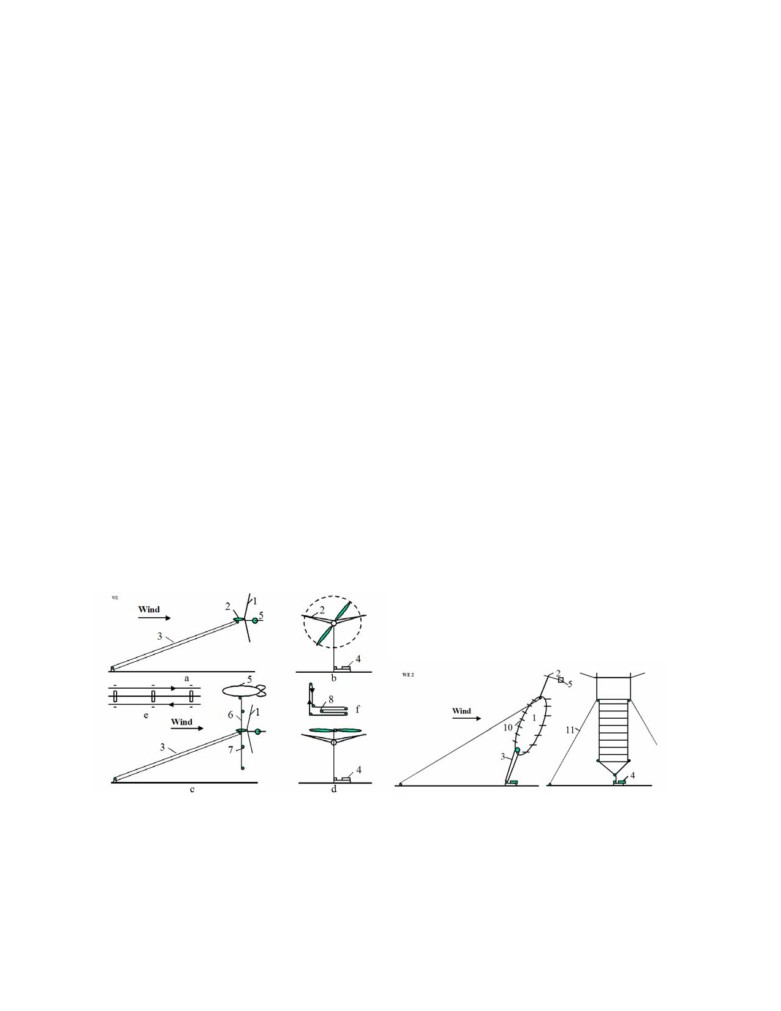
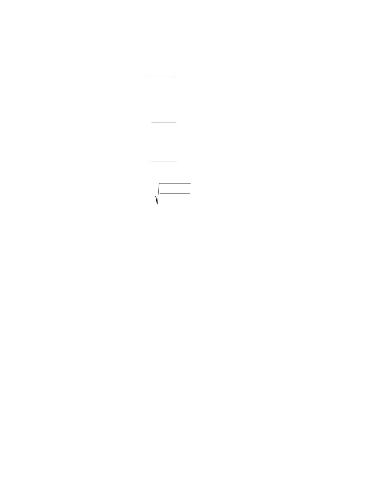
Main proposed high altitude wind system is presented in fig.5. That includes: rotor (turbine) 1,
support wing 2, cable mechanical transmission and keep system 3, electro-generator 4, and stabilizer 5.
The transmission system has three cables (fig.5e): main (central) cable, which keeps the rotor at a
given altitude, and two transmission mobile cables, which transfer energy from the rotor to the ground
electric generator. The device of fig.5f allows changing a cable length and a rotor altitude. In calm
weather the rotor can be support at altitude by dirigible 9 (fig.5c) or that is turned in vertical position
and support by rotation from the electric generator (fig.5d). If the wind is less of a minimum speed for
support of rotor at altitude the rotor may be supported by autogiro mode in position of fig.6d. The
probability of full wind calm at a high altitude is small and depends from an installation location.
Fig.6 shows other design of the proposed high altitude wind installation. This rotor has blades, 10,
connected to closed-loop cables. The forward blades have a positive angle and lift force. When they
are in a back position the lift force equals zero. The rotor is supported at the high altitude by the blades
and the wing 2 and stabilizer 5. That design also has energy transmission 3 connected to the ground
electric generator 4.
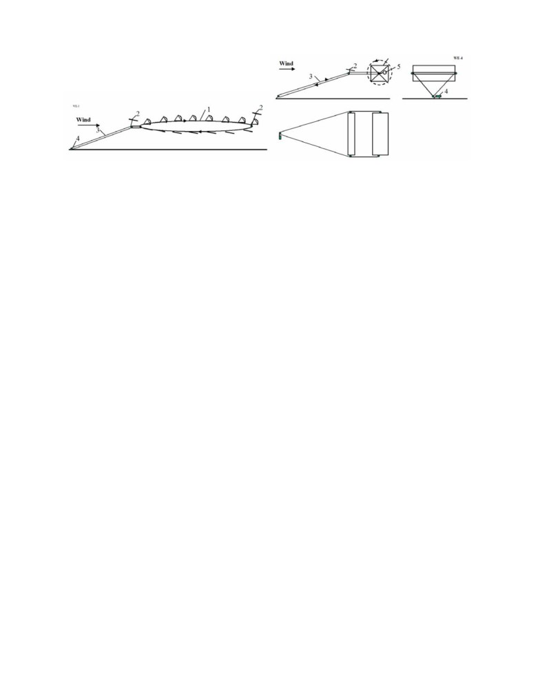
Fig.7. shows a parachute wind high altitude installation. Here the blades are changed by parachutes.
The parachutes have a large air drag and rotate the cable rotor 1. The wind 2 supports the installation
in high altitude. The cable transmission 3 passes the rotor rotation to the ground electric generator 4.
A system of fig.8 uses a large Darries air turbine located at high altitude. This turbine has four blades.
The other components are same with previous projects.
Problems of launch, start, guidance, control, stability, and others
Launching. It is not difficult to launch the installations having support wing or blades as described in
fig. 5-8. If the wind speed is more than the minimum required speed (>2-3 m/s), the support wing lifts
the installation to the desired altitude.
Starting. All low-speed rotors are self-starting. All high-speed rotors require an initial starting
rotation from the ground motor-generator 4 (fig.5).
Fig.5 (left). Propeller high altitude wind energy installation and cable energy transport system. Notation: a -
side view;
1 - wind rotor; 2 - wing with ailerons; 3 - cable energy transport system; 4 - electric
generator; 5 - stabilizer; b - front view; c - side view with a support dirigible 9, vertical cable 6, and wind
speed sensors 7; d - keeping of the installation at a high altitude by rotate propeller; e - three lines of the
transmission - keeper system. That includes: main (central) cable and two mobile transmission cables; f -
energy transport system with variable altitude; 8 - mobile roller.
Fig.6 (right). High altitude wind energy installation with the cable turbine. Notation: 10 - blades; 11 - tensile
elements (bracing)(option).
6
Fig.7 (left). High altitude wind energy installation with the parachute turbine.
Fig.8 (right). High altitude wind energy installation with Darrieus turbine.
Guidance and Control. The control of power, revolutions per minute, and torque moment are
operated by the turning of blades around the blade longitudinal axis. The control of altitude may be
manual or automatic when the wind speed is normal and over admissible minimum. Control is effected
by wing flaps and stabilizer (elevator), fin, and ailerons (figs. 5-8).
Stability. Stability of altitude is produced by the length of the cable. Stability around the blade
longitudinal axis is made by stabilizer (see figs.5,6,8). Rotor directional stability in line with the flow
can be provided by fins (figs. 5). When the installation has the support wing rigidly connected to the
rotor, the stability is also attained by the correct location of the center of gravity of the installation
(system rotor-wing) and the point of connection of the main cable and the tension elements. The
center-of-gravity and connection point must be located within a relatively narrow range 0.2-0.4 of the
average aerodynamic chord of the support wing (for example, see fig.5). There is the same requirement
for the additional support wings such as fig.6-8.
Torque moment is balanced by transmission and wing ailerons (see figs.5-8).
The wing lift force, stress of main cable are all regulated automatic by the wing flap or blade
stabilizer.
The location of the installation of fig.6 at a given point in the atmosphere may be provided by
tension elements shown on fig.6. These tension elements provide a turning capability for the
installation of approximately ± 450 degrees in the direction of flow (see. Fig.6.).
Minimum wind speed. The required minimum wind-speed for most of the suggested installation
designs is about 2 m/s. The probability of this low wing speed at high altitude is very small (less
0.001). This minimum may be decreased still further by using the turning propeller in an autogiro
mode. If the wind speed is approximately zero, the rotor can be supported in the atmosphere by a
balloon (dirigible) as is shown on fig.1c or a propeller rotated by the ground power station as is shown
on fig.2d. The rotor system may also land on the ground and start again when the wind speed attains
the minimum speed for flight.
A Gusty winds. Large pulsations of wind (aerodynamic energy) can be smoothed out by inertial fly-
wheels.
The suggested Method and Installations for utilization of wind energy has following peculiarities
from current conventional methods and installations:
1. Proposed installation allows the collection of energy from a large area - tens and even hundreds of
times more than conventional wind turbines. This is possible because an expensive tower is not
needed to fix our rotor in space. Our installation allows the use of a rotor with a very large
diameter, for example 100-200 meters or more.
2. The proposed wind installations can be located at high altitude 100 m - 14 km. The wind speeds are
2-4 times faster and more stable at high altitude compared to ground surface winds used by the
7
altitude of conventional windmills (10-70 meters of height). In certain geographic areas high
altitude wind flows have a continuous or permanent nature. Since wind power increases at the
cube of wind speed, wind rotor power increases by 27 times when wind speed increases by 3 times.
3.
In proposed wind installation the electric generator is located at ground. There are proposals where
electric generator located near a wind rotor and sends electric current to a ground by electric wares.
However, our rotor and power are very large (see projects below). Proposed installations produce
more power by thousands of times compared to the typical current wind ground installation (see
point 1, 2 above). The electric generator of 20 MW weighs about 100 tons (specific weigh of the
conventional electric generator is about 3-10 kg/kW). It is impossible to keep this weigh by wing at
high altitude for wind speed lesser then 150 m/s.
4.
One of the main innovations of the given invention is the cable transfer (transmission) [5] of
energy from the wind rotor located at high altitude to the electric generator located on ground. In
proposed Installation it is used a new cable transmission made from artificial fibers. This
transmission has less a weigh in thousands times then copper electric wires of equal power. The
wire having diameter more 5 mm passes 1-2 ampere/sq.mm. If the electric generator produces 20
MW with voltage 1000 Volts, the wire cross-section area must be 20,000 mm2, (wire diameter
is160 mm). The cross-section area of the cable transmission of equal power is only 37 mm2 (cable
diameter 6.8 mm2 for cable speed 300 m/s and admissible stress 200 kg/mm2, see Project 1). The
specific weight of copper is 8930 kg/m3, the specific weight of artificial fibers is 1800 kg/m3. If the
cable length for altitude 10 km is 25 km the double copper wire weighs 8930 tons (!!), the fiber
transmission cable weighs only 3.33 tons. It means the offered cable transferor energy of equal
length is easier in 2682 times, then copper wire. The copper wires is very expensive, the artificial
fiber is cheap.
All previous attempts to place the generator near the rotor and connect it to ground by electric
transmission wires were not successful because the generator and wires are heavy.
Information about Wind Energy at high altitude
The power of a wind engine strongly depends on the wind speed (to the third power). Low altitude
wind (H = 10 m) has the standard average speed V = 6 m/s. High altitude wind is powerful and that has
another important advantage, it is stable and constant. This is true practically everywhere.
Wind in the troposphere and stratosphere are powerful and permanent. For example, at an altitude of
5 km, the average wind speed is about 20 M/s, at an altitude 10-12 km the wind may reach 40 m/s (at
latitude of about 20-350N).
There are permanent jet streams at high altitude. For example, at H = 12-13 km and about 250N
latitude. The average wind speed at its core is about 148 km/h
(41 m/s). The most intensive portion,
with a maximum speed 185 km/h (51 m/s) latitude 220, and 151 km/h (42 m/s) at latitude 350 in North
America. On a given winter day, speeds in the jet core may exceed 370 km/h (103 m/s) for a distance
of several hundred miles along the direction of the wind. Lateral wind shears in the direction normal to
the jet stream may be 185 km/h per 556 km to right and 185 km/h per 185 km to the left.
The wind speed of V = 40 m/s at an altitude H = 13 km provides 64 times more energy than surface
wind speeds of 6 m/s at an altitude of 10 m.
This is a gigantic renewable and free energy source. (See reference: Science and Technolody,v.2,
p.265).
Cable transmission of wind energy [5]
The primary innovations presented in this paper are locating the rotor at high altitude, and an energy
transfer system using a cable to transfer mechanical energy from the rotor to a ground power station.
The critical factor for this transfer system is the weight of the cable, and its air drag.
8
Twenty years ago, the mass and air drag of the required cable would not allow this proposal to be
possible. However, artificial fibers are currently being manufactured, which have tensile strengths of
3-5 times more than steel and densities 4-5 times less then steel. There are also experimental fibers
(whiskers) which have tensile strengths 30-100 times more than a steel and densities 2 to 5 times less
than steel. For example, in the book [6] p.158 (1989), there is a fiber (whisker) CD, which has a tensile
strength of σ = 8000 kg/mm2 and density (specific gravity) of γ = 3.5 g/cm3. If we use an estimated
strength of 3500 kg/mm2 (σ =7.1010 N/m2, γ = 3500 kg/m3), then the ratio is γ/σ = 0.1×10⁻⁶ or σ/γ =
10×106. Although the described (1989) graphite fibers are strong (σ/γ = 10×106), they are at least still
ten times weaker than theory predicts. A steel fiber has a tensile strength of
5000 MPA (500
kg/sq.mm), the theoretical limit is 22,000 MPA (2200 kg/mm2)(1987); the polyethylene fiber has a
tensile strength 20,000 MPA with a theoretical limit of 35,000 MPA (1987). The very high tensile
strength is due to its nanotubes structure.
Apart from unique electronic properties, the mechanical behavior of nanotubes also has provided
interest because nanotubes are seen as the ultimate carbon fiber, which can be used as reinforcements
in advanced composite technology. Early theoretical work and recent experiments on individual
nanotubes (mostly MWNT’s, Multi Wall Nano Tubes) have confirmed that nanotubes are one of the
stiffest materials ever made. Whereas carbon-carbon covalent bonds are one of the strongest in nature,
a structure based on a perfect arrangement of these bonds oriented along the axis of nanotubes would
produce an exceedingly strong material. Traditional carbon fibers show high strength and stiffness, but
fall far short of the theoretical, in-plane strength of graphite layers by an order of magnitude.
Nanotubes come close to being the best fiber that can be made from graphite.
For example, whiskers of Carbon nanotube (CNT) material have a tensile strength of 200 Giga-
Pascals and a Young’s modulus over 1 Tera Pascals (1999). The theory predicts 1 Tera Pascals and a
Young’s modules of 1-5 Tera Pascals. The hollow structure of nanotubes makes them very light (the
specific density varies from 0.8 g/cc for SWNT’s (Single Wall Nano Tubes) up to 1.8 g/cc for
MWNT’s, compared to 2.26 g/cc for graphite or 7.8 g/cc for steel).
Specific strength (strength/density) is important in the design of the systems presented in this paper;
nanotubes have values at least 2 orders of magnitude greater than steel. Traditional carbon fibers have
a specific strength 40 times that of steel. Since nanotubes are made of graphitic carbon, they have good
resistance to chemical attack and have high thermal stability. Oxidation studies have shown that the
onset of oxidation shifts by about 1000 C or higher in nanotubes compared to high modulus graphite
fibers. In a vacuum, or reducing atmosphere, nanotube structures will be stable to any practical service
temperature.
The artificial fibers are cheap and widely used in tires and everywhere. The price of SiC whiskers
produced by Carborundum Co. with σ=20,690 MPa and γ=3.22 g/cc was $440 /kg in 1989. The market
price of nanotubes is too high presently (~$200 per gram)(2000). In the last 2-3 years, there have been
several companies that were organized in the US to produce and market nanotubes. It is anticipated
that in the next few years, nanotubes will be available to consumers for less than $100/pound.
Below, the author provides a brief overview of recent research information regarding the proposed
experimental (tested) fibers. In addition, the author also addresses additional examples, which appear
in these projects and which can appear as difficult as the proposed technology itself. The author is
prepared to discuss the problems with organizations which are interested in research and development
related projects.
9
Table # 1. Material properties.
Material
Tensile
Density
Fibers
Tensile
Density
strength
g/cc
strength
g/cc
Whiskers
kg/mm2
kg/mm2
AlB12
2500
2.6
QC-8805
620
1.95
B
2650
2.3
TM9
600
1.79
B4C
2800
4.5
Thorael
565
1.81
TiB2
3370
2.5
Allien 1
580
1.56
SiC
1380-
3.22
Allien 2
300
0.97
4140
Reference [6]-[9].
Industrial fibers with σ = 500-600 kg/mm2, γ = -1800 kg/m3, and σ⁄γ = 2,78x10⁶ are used in all our
projects (admissible σ =200-250 kg/mm2)(see below).
Theory of Suggested Installations
Rotor
Power of a wind energy N [Watt, Joule/sec]
N=0.5ηρAV3
[W] .
(1)
The coefficient of efficiency, η, equals
0.15-0.35 for low speed rotors (ratio of blade tip speed to
wind speed equals λ ≈ 1); η = 0.35-0.5 for high speed rotors (λ = 5-7). The Darrieus rotor has η = 0.35
- 0.4. The propeller rotor has η = 0.45-0.50. The theoretical maximum equals η = 0.67.
The energy is produced in one year is (1 year ≈ 30.2×10⁶ work sec) [J]
E=3600×24×350 ≈ 30×106N
[J].
(1’)
Wind speed increases with altitude as follows
V=(H/Ho)αVo ,
(2)
where α = 0.1 - 0.25 exponent coefficient depends from surface roughness. When the surface is
water, α = 0.1; when surface is shrubs and woodlands α = 0.25 .
Power increases with altitude as the cube of wind speed
N=(H/Ho)3αNo ,
(3)
where No is power at Ho.
The drag of the rotor equals
Dr=N/V .
(4)
The lift force of the wing, Ly , is
Ly=0.5CLρV2Aw
, Ly≈W ,
(5)
where CL is lift coefficient (maximum CL ≈ 2.5), Aw is area of the wing, W is weight of installation +
0.5 weight of all cables.
The drag of the wing is
D = 0.5CDρV2Aw ,
(6)
where CD is the drag coefficient (maximum CD ≈1.2) .
The optimal speed of the parachute rotor equals 1/3V and the theoretical maximum of efficiency
coefficient is 0.5 .
The annual energy produced by the wind energy extraction installation equals
E=8.33N
[kWh] .
(7)
Cable Energy Transfer, Wing Area, and other Parameters
Cross-section area of transmission cable, S , is
S=N/vσ ,
(8)
Cross-section area of main cable, Sm , is
10
Sm=(Dr+D)/σ ,
(8’)
Weight of cable is
Wr=SLγ ,
(9)
The production cost, c, in kWh is
M +I/K
1
c
=
,
(10)
E
The annual profit
F= (C-c)E .
(11)
The required area of the support wing is
ηAsin
θ
A
=
,
(12)
w
C
L
where θ is the angle between the support cable and horizontal surface.
The wing area is served by ailerons for balancing of the rotor (propeller) torque moment
AR
= η
,
(13)
Aa
λ
ΔC
r
i
L,a
The minimum wind speed for installation support by the wing alone
2W
=
,
(14)
Vmin
C
ρA
L,max
w
where W is the total weight of the airborne system including transmission. If a propeller rotor is used
in a gyroplane mode, minimal speed will decrease by 2-2,5 times. If wind speed equals zero, the
required power for driving the propeller in a propulsion (helicopter) mode is
Ns = W/K2
[kW],
(15)
The specific weight of energy storage (flywheel) can be estimated by
Es=σ/2γ
[J/kg].
(16)
For example, if σ =200 kg/mm2, γ =1800 kg/m3, then Es=0.56 MJ/kg or Es=0.15 kWh/kg.
For comparison of the different ground wind installations their efficiency and parameters are
computed for the standard wind conditions: the wind speed equals V=6 m/s at the altitude H=10 m.
Projects
Project 1
High-speed air propeller rotor (fig.5)
For example, let us consider a rotor diameter of 100 m (A = 7850 m2), at an altitude H = 10 km (ρ =
0.4135 kg/m3), wind speed of V = 30 m/s , an efficiency coefficient of η = 0.5, and a cable tensile
stress of σ = 200 kg/mm2 .
Then the power produced is N = 22 MW [Eq. (1)], which is sufficient for city with a population of
250,000. The rotor drag is Dr = 73 tons [Eq.(4)], the cross-section of the main cable area is S =1.4Dr/ı
=l.35×73/0.2 ≈ 500 mm2, the cable diameter equals d =25 mm; and the cable weight is W =22.5 tons
[Eq.(9)] (for L=25 km). The cross-section of the transmission cable is S = 36.5 mm2 [Eq.(8)], d = 6.8
mm, weight of two transmission cables is W = 3.33 tons for cable speed v =300 m/s [Eq.(9)].
The required wing size is 20×100 m (CL=0.8) [Eq.(12)], wing area served by ailerons is 820 sq.m
[Eq.(13)]. If CL=2, the minimum speed is 2 m/s [Eq.(14)].
The installation will produce an annual energy E =190 GWh [Eq.(7)]. If the installation cost is
$200K, has a useful life of 10 years, and requires maintenance of $50K per year, the production cost is
c = 0.37 cent per kWh [Eq(10)]. If retail price is $0.15 per kWh, profit $0.1 per kWh, the total annual
profit is $19 millions per year [Eq.(11)].
11
The project #2
Large air propeller at altitude H = 1 km (fig.5)
Let us consider a propeller diameter of 300 m, with an area A = 7×10⁴ m2, at an altitude H = 1 km, and
a wind speed of 13 m/s. The average blade tip speed is 78 m/s.
The full potential power of the wind streamer flow is 94.2 MW. If the coefficient of efficiency is 0.5
the useful power is N = 47.1 MW. For other wind speed. the useful power is: V = 5 m/s, N = 23.3
MW; V = 6 m/s, N = 47.1 MW; V = 7 m/s, N = 74.9 MW; V = 8 m/s, N = 111.6 MW; V = 9 m/s, N =
159 MW; V = 10 m/s, N =218 MW.
Estimation of economical efficiency
Let us assume that the cost of the Installation is $3 million, a useful life of 10 years, and request
maintenance of $100,000/year. The energy produced in one year is E = 407 GWh [Eq.(7)]. The basic
cost of energy is $0.01 /kWh.
The some technical parameters
Altitude H = 1 km
The drag is about 360 tons. Ground connection (main) cable has cross-section area of 1800 sq,mm
[Eq.(8’)], d = 48 mm, and has a weight of 6480 kg. The need wing area is 60x300 m. The aileron area
requested for turbine balance is 6740 sq.m.
If the transmission cable speed is 300 m/s, the cross-section area of transmission cable is 76 sq.mm
and the cable weight is 684 kg (composite fiber).
Altitude H = 13 km
At an altitude of H =13 km. the air density is ȡ=0.2666, and the wind speed is V = 40 m/s. The power
for efficiency coefficient 0.5 is 301.4 MgW. The drag of the propeller is approximately 754 tons. The
connection cable has a cross-sectional area of 3770 sq.mm, a diameter is d =70 mm and a weight of
176 tons. The transmission cable has a sectional area 5 sq.c and a weight of 60 tons (vertical
transmission only 12 tons).
The installation will produce energy E=2604 GWh per year. If the installation costs $5 million,
maintenance is $200,000/year, and the cost of 1 kWh will be $0.0097/kWh.
Project #3
Air low speed wind engine with free flying cable flexible rotor (fig.6)
Let us consider the size of cable rotor of width 50 m, a rotor diameter of 1000 m, then the rotor area
is A=50×1000=50,000 sq.m. The angle rope to a horizon is 70o. The angle of ratio lift/drag is about
2.5o.
The average conventional wind speed at an altitude H = 10 m is V = 6 m/s. It means that the speed at
the altitude 1000 m is 11.4 - 15 m/s. Let us take average wind speed V=13 m/s at an altitude H = 1 km.
The power of flow is
N=0.5.ρV3Acos200=0.5×1.225×133×1000×50×0.94=63 MW .
If the coefficient efficiency is η = 0.2 the power of installation is
η = 0.2×63 = 12.5 MW .
The energy 12.5 MW is enough for a city with a population at 150,000.
If we decrease our Installation to a 100x2000 m the power decreases approximately by 6 times
(because the area decreases by 4 times, wind speed reaches more 15 m/s at this altitude. Power will be
75 MW. This is enough for a city with a population about 1 million of people.
If the average wind speed is different for given location the power for the basis installation will be: V
=5 m/s, N =7.25 MW; V =6 m/s, N =12.5 MW; V=7 m/s, N = 19.9 MW; V = 8 m/s, N = 29,6 MW;
V = 9 m/s, N = 42.2 MW; V = 10 m/s, N = 57.9 MW.
Economical efficiency
Let us assume that the cost of our installation is $1 million. According to the book “Wind Power” by
P. Gipe [2], the conventional wind installation with the rotor diameter 7 m costs $20,000 and for
average wind speeds of 6 m/s has power 2.28 kW, producing 20,000 kWh per year. To produce the
12
same amount of power as our installation using by conventional methods, we would need 5482
(12500/2.28) conventional rotors, costing $110 million. Let us assume that our installation has a
useful life of 10 years and a maintenance cost is $50,000/year. Our installation produces 109,500,000
kWh energy per year. Production costs of energy will be approximately 150,000/109,500,000 = 0.14
cent/kWh. The retail price of 1 kWh of energy in New York City is $0.15 now. The revenue is 16
millions. If profit from 1 kWh is $0.1, the total profit is more 10 millions per year.
Estimation some technical parameters
The cross-section of main cable for an admissible fiber tensile strange σ = 200kg/sq.mm is S
=2000/0.2 = 10,000 mm2. That is two cable of diameter d =80 mm. The weight of the cable for density
1800 kg/m3 is
W = SLγ = 0.01×.2000×.1800 = 36 tons .
Let us assume that the weight of 1 sq.m of blade is 0.2 kg/m2 and the weight of 1 m of bulk is 2 kg.
The weight of the 1 blade will be 0.2 x 500 = 100 kg, and 200 blades are 20 tons. If the weight of one
bulk is 0.1 ton, the weight of 200 bulks is 20 tons.
The total weight of main parts of the installation will be 94 tons. We assume 100 tons for purposes of
our calculations.
The minimum wind speed when the flying rotor can supported in the air is (for Cy = 2)
V=(2W/CyρS)0.5=(2×100×104/2×1.225×200×500)0.5 = 2.86 m/s
The probability of the wind speed falling below 3 m/s when the average speed is 12 m/s, is zero, and
for 10 m/s is 0.0003. This equals 2.5 hours in one year, or less than one time per year. The wind at high
altitude has greater speed and stability than near ground surface. There is a strong wind at high altitude
even when wind near the ground is absent. This can be seen when the clouds move in a sky on a calm
day.
Project #4
Low speed air drag rotor (fig.7)
Let us consider a parachute with a diameter of 100 m, length of rope 1500 m, distance between the
parachutes 300 m, number of parachute 3000/300 = 10, number of worked parachute 5, the area of one
parachute is 7850 sq.m, the total work area is A = 5 x 7850 = 3925 sq.m. The full power of the flow is
5.3 MW for V=6 m/s. If coefficient of efficiency is 0.2 the useful power is N = 1 MW. For other wind
speed the useful power is: V =5 m/s, N =0.58 MW; V =6 m/s, N = 1 MW; V =7 m/s, N =1.59 MW; V
= 8 m/s, N=2.37 MW; V = 9 m/s, N =3.375 MW; V = 10 m/s, N = 4.63 MW.
Estimation of economical efficiency
Let us take the cost of the installation $0.5 million, a useful life of 10 years and maintenance of
$20,000/year. The energy produced in one year (when the wind has standard speed 6 m/s) is E =
1000x24x360 = 8.64 million kWh. The basic cost of energy is 70,000/8640,000 = 0.81 cent/kWh.
The some technical parameters
If the thrust is 23 tons, the tensile stress is 200 kg/sq.mm (composed fiber), then the parachute cable
diameter is 12 mm, The full weight of the installation is 4.5 tons. The support wing has size 25x4 m.
Project #5
High speed air Darreus rotor at an altitude 1 km (fig.8)
Let us consider a rotor having the diameter of 100 m, a length of 200 m (work area is 20,000 sq.m).
When the wind speed at an altitude H=10 m is V =6 m/s, then at an altitude H = 1000 m it is 13 m/s.
The full wind power is 13,46 MW. Let us take the efficiency coefficient 0.35, then the power of the
Installation will be N = 4.7 MW. The change of power from wind speed is: V = 5 m/s, N = 2.73 MW;
V = 6 m/s, N = 4.7 MW; V = 7 m/s, N = 7.5 MW; V = 8 m/s, N = 11.4 MW; V = 9m/s, N = 15.9 MW;
V = 10 m/s, N = 21.8 MW.
At an altitude of H = 13 km with an air density 0.267 and wind speed V = 40 m/s, the given
installation will produce power N = 300 MW.
Estimation of economical efficiency
13
Let us take the cost of the Installation at $1 million, a useful life of 10 years, and maintenance of
$50,000 /year. Our installation will produce E = 41 millions kWh per year
(when the wind speed
equals 6 m/s at an altitude 10 m). The prime cost will be 150,000/41,000,000 = 0.37 cent/kWh. If the
customer price is $0.15/kWh and profit from 1 kWh is $0.10 /kWh the profit will be $4.1 million per
year.
Estimation of technical parameters
The blade speed is 78 m/s. Numbers of blade is 4. Number of revolution is 0.25 revolutions per
second. The size of blade is 200x0.67 m. The weight of 1 blade is 1.34 tons. The total weight of the
Installation is about 8 tons. The internal wing has size 200x2.3 m. The additional wing has size
200x14.5 m and weight 870 kg. The cross-section area of the cable transmission having an altitude of
H = 1 km is 300 sq.mm, the weight is 1350 kg.
Other projects
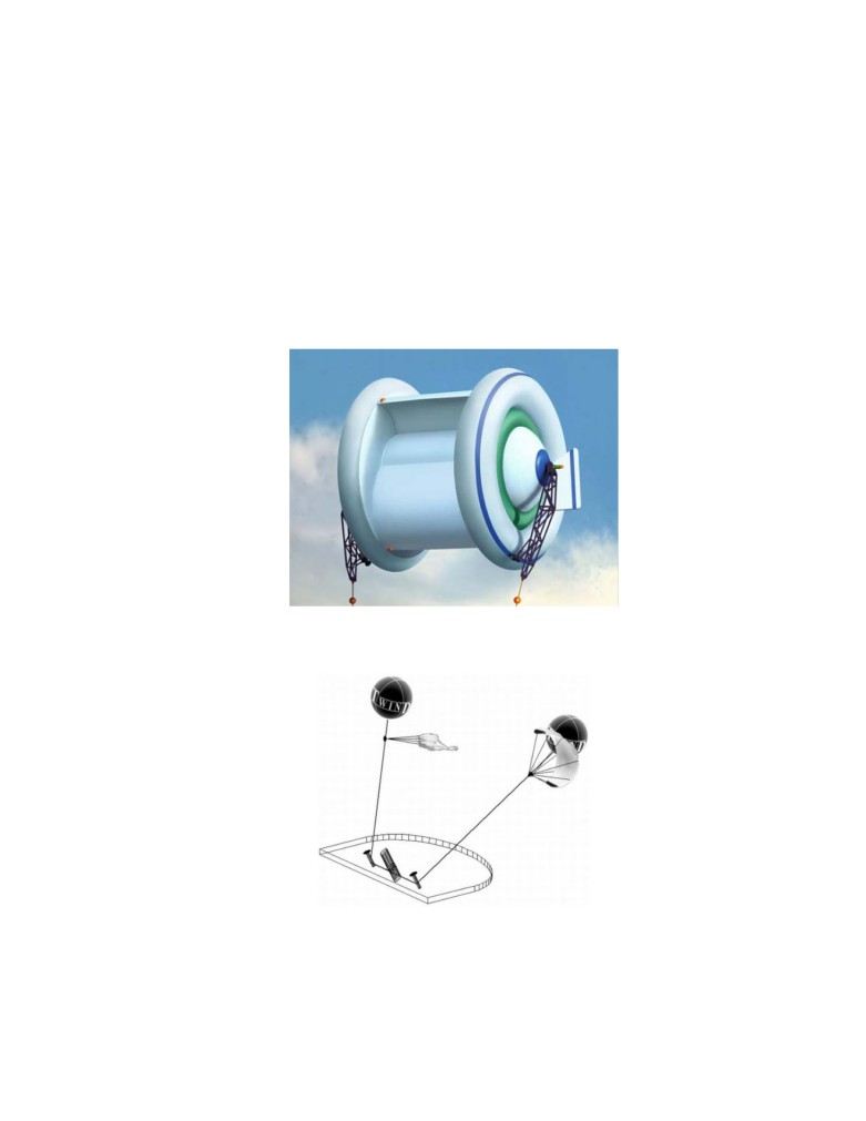
Some other projects are shown in figs. 9 - 10.
Fig.9. Some proposals of aerial wind turbines. The Magenn Power wind turbine, called MARS, differs from a kite-
style wind power system in that it’s held aloft by helium rather than relying on the force of wind. Lack: One cannot
use a strong wind and high altitudes.
Fig.10. NASA project of wind-engine. Air balloons and parachutes. Lack: One cannot use a strong wind
and high altitudes.
Discussion and Conclusion
Conventional windmills are approached their maximum energy extraction potential relative to their
installation cost. No relatively progress has been made in windmill technology in the last 50 years. The
14
wind energy is free, but its production more expensive then its production in heat electric stations.
Current wind installations cannot essential decrease a cost of kWh, stability of energy production.
They cannot increase of power of single energy unit. The renewable energy industry needs
revolutionary ideas that improve performance parameters (installation cost and power per unit) and
that significantly decreases (in 10-20 times) the cost of energy production. This paper offers ideas that
can move the wind energy industry from stagnation to revolutionary potential.
The following is a list of benefits provided by the proposed system compared to current installations:
1. The produced energy at least in 10 times cheaper then energy received of all conventional electric
stations includes current wind installation.
2. The proposed system is relatively inexpensive (no expensive tower), it can be made with a very
large thus capturing wind energy from an enormous area (hundreds of times more than typical
wind turbines).
3. The power per unit of proposed system in some hundreds times more of typical current wind
installations.
4. The proposed installation not requires large ground space.
5. The installation may be located near customers and not require expensive high voltage equipment.
It is not necessary to have long, expensive, high-voltage transmission lines and substations. Ocean
going vessels can use this installation for its primary propulsion source.
6. No noise and bad views.
7. The energy production is more stability because the wind is steadier at high altitude. The wind may
be zero near the surface but it is typically strong and steady at higher altitudes. This can be
observed when it is calm on the ground, but clouds are moving in the sky. There are a strong
permanent air streams at a high altitude at many regions of the USA.
8. The installation can be easy relocated in other place.
As with any new idea, the suggested concept is in need of research and development. The theoretical
problems do not require fundamental breakthroughs. It is necessary to design small, free flying
installations to study and get an experience in the design, launch, stability, and the cable energy
transmission from a flying wind turbine to a ground electric generator.
This paper has suggested some design solutions from patent application [4]. The author has many
detailed analysis in addition to these presented projects. Organizations interested in these projects can
The other ideas are in [1]-[5], [10]-[13].
References
http://www.scribd.com/doc/24056182; “New concepts, Ideas, and Innovation in Aerospace, Technology and
Human Science”, NOVA, 2007, 502 pgs., http://www.scribd.com/doc/24057071; Macro-Projects: Environment
and Technology, NOVA, 2008, 536 pgs., http://www.scribd.com/doc/24057930; “New Technologies and
1. Bolonkin A.A., Utilization of Wind Energy at High Altitude,. International Energy Conversion Engineering
Conference at Providence, RI, USA, Aug.16-19, 2004. AIAA-2004-5756, AIAA-2004-5705,
2. Gipe P., Wind Power, Chelsea Green Publishing Co., Vermont, 1998.
3. Thresher R.W. and etc, Wind Technology Development: Large and Small Turbines, NRFL, 1999.
4. Bolonkin, A.A.,
”Method of Utilization a Flow Energy and Power Installation for It”, USA patent
application 09/946,497 of 09/06/2001.
5. Bolonkin, A.A., Transmission Mechanical Energy to Long Distance.AIAA-2004-5660. AIAA Conference
2004.
15
6. Galasso F.S., Advanced Fibers and Composite, Gordon and Branch Scientific Publisher, 1989.
7. Carbon and High Performance Fibers Directory and Data Book, London-New. York: Chapmen& Hall,
1995, 6th ed., 385 p.
8. Concise Encyclopedia of Polymer Science and Engineering, Ed. J.I.Kroschwitz, N. Y.,Wiley, 1990, 1341 p.
9. Dresselhaus, M.S., Carbon Nanotubes, Springer, 2000.
10. Bolonkin, A.A., Femtotechnology: Nuclear AB-Material with Fantastic Properties. 2009,
11. Bolonkin, A.A., Femtotechnology: Design of the Strongest AB-Matter for Aerospace, 2009,
12. Bolonkin, A.A., Converting of Any Matter to Nuclear Energy by-AB-Generator , 2009,
13. Bolonkin, A.A., Converting of any Matter to Nuclear Energy by AB-Generator and Aerospace , 2009,
Work was written in 2000, patented in 2001, corrected in 2009.