Editors may edit
your note. We won't publish your e-mail unless separate direct permission is
granted. E-mail or send link to your images, drawings, photographs, plans,
documents:
Notes@EnergyKiteSystems.net ABCDEFGHIJKLMNOPQRSTUVWXYZ,
or other AWE matters.
Sky Wind Power pre-incorporation
associated photo of 1986:
http://www.skywindpower.com/ww/Aust-test.htm
Upon the courtesy of PJ Shepard and her research:
[[The "myself" in the paragraph below is Bryan Roberts.]]
Bryan replied and said,
"This photo was taken, I believe, on or about May 1986.
The twin-rotor craft was approx. in the autorotation state in the photo.
Generation was done briefly in another test, which is shown in the video
attached to the SWP website. [[Videos]]
The craft had rotors 12 feet in diameter and weighed 64 lbs. The people in
the photo ( reading from left to right in the photo) are Hasso Nibbe, Alan
Fien, Grahame Levitt and myself. All were employees of the University of
Sydney. The tests were undertaken on the University's "Mt. Pleasant Farm" at
Marulan in New South Wales. The wind was onto our backs at about 15 knots
thereabouts."
Last week I drew this Gorlov TurboSail design of
the earlier sketch while on a 10 hour flight to Israel. It could mean a marked
improvement over what Jacques Cousteau had on the Alcyone ship! I find myself
humming the Calypso song by John Denver on occasion now when I think about how
cool it would be if this concept really did improve what he pioneered with his TurboSail invention!
As you have noticed, by my email address, I no longer desire to go by the
name, Darin. It doesn't fit me over here when I introduce myself to the
locals. I'm also in the process of learning the Hebrew language, and immersing
myself into their culture. My friend here said to me that it would be good to
change my name to a Hebrew one, and then suggested the name, David,
(pronounced Da-veed). I had always secretly liked that name, so it was easy to
say yes.
Though, it has been tough to remember that I've changed it, when introducing
myself to people. It shows to me how much of a "programmed rat" I've become in
my communication skills. So, it is high-time for me to bust out of the U.S.
box that I've place myself in!
My hopes in presenting these many concepts with you and others, is that
through this AWE community effort, tangible working prototypes could possibly
be made. In many ways, through your enthusiastic attention to kite power, it
has inspired me to continue with my drawings, because now I have really
constructive chat room of like-minded individuals to share them in!
~David Inisrael, December 2 , 2009.
This is an example of the VAWT of Darrieus being set as needed with axis
traverse to wind, but here horizontal; but this does not quality the machine to
be classed as HAWT, as it is does not have the axis parallel to stream, as it
would not then work.
How
might kites be used to clear mines from war fields? Demining is dangerous
activity. Mines injure people decades after the mines were set in the ground.
Notice how
AeroCam
seems to be the contemporary user of the VAWT set horizontally without
becoming HAWT machine. Shepard aimed at AWECS. AeroCam at
Broadstar is back on the ground. Now, perhaps some "AWEiflying" of
the Darrieus will occur.
http://www.mariahpower.com/ are non-AWE, but Shepard had
instructed the AWECS version. Same device works at any clock
angle, so long as the axis is traverse to the wind, as Darrieus instructed
in his early 1925 and 1926 patents. At altitude lifted via AWE
tactics, we get a family of H-Darrieus that remain VAWT even though axis
can be at any angle so long as the axis is normal to stream.
Seems like Macedo instructs lifting planes as well as
blimps or lifting aerostats or kytoons in concert. Seemingly
related is a recent patent instruction by Aleandro Soares Macedo:
Filed: October 31, 2004
No companies yet known to be associated with this patent.
"A
power generator comprising: a lifting body for suspension in a
moving fluid; a control station; and at least two tethers for tethering the
lifting body to the control station. The control station is arranged to
transform oscillating tension in the tethers produced by an oscillating
movement of..."
Non-awe,
but someone will
"AWEifly"
it with some lifters!
Wing energy catchment device
Manuel Munoz Saiz Wind energy catchment device that consists of loops of closed circuits of
cables or ropes which go through a succession of parachutes in series, that
rotates by means of pulleys among columns, pylons or shafts secured to rigid
supports fixed to the ground, the cables go through the parachutes by...
My to-all AWE query or note: of Dec. 1:
Ever-up AWECS is a lofty ideal that should be pursued. Cost is however critical.
Perhaps storage may cover for down-AWECS moments as in current inverter-systems.
Anonymous.
Drawing does not show
the possible effective kytoon with better L/D to handle higher winds.
The crossbeam could
hold a working Darrieus or Savonius.
The tethers could be
spread footed and enable holding a full chain of turbines to infill the
available space. 1000 m of two strings of turbines. The hung turbines would be
HAWT. The spreaders could be VAWT set with axis horizontal.
If generator is wanted
on ground, then have bullwheels driving infinite loops to the generator or
water pump.
Torque
shaft to "flying" rotating devices. Torque goes to groundstation and
generator.
A thin carbon nanotube tether could be attached to the photon kite; the tether
could be moored to an asteroid. Perhaps a camera could be mounted to the kite.
The camera would occasionally bleep video data to a receiver for our viewing the
asteroid.
A comprehensive treatment of rotary kites would face several species of
both horizontal axis and vertical axis and oblique axis rotary kites. There are
Magnus-effect kites and non-Magnus effect rotary kites. Rotary kites in several
species have a long history in comercial kiting, military kiting, festival
kiting, and kite energy conversion systems. The patent depth is deep on rotary
kites. The effect on green cleantech from rotary kites is growing in the
research and development in several companies. Significant impacts within high
altitude wind power are current news points. The dynamics of rotary kites are
quite a bit more complex than for non-rotary kites. The SkyMill Energy kite is a
rotary kite. The Magenn Power kytoon is a rotary kite. The Joby Energy kite will
be a hybrid rotary kite that has lifting surfaces that are not rotating and
lifting rotary parts that are generating electricity aloft. David H. Shepard got
a couple of key patents approved for rotary kites. The Sky WindPower company is
fully focused on rotary kites. Someone should start an article on Rotary kites
and the other terms Rotary kite and Rotary Kite should redirect to the one
leading article where links can go to specific historical special rotary kites
like those used in military observation from ships and submarines. There is also
the exact important inclusion to be involved...where the fluid for the rotary
kites actions is water. Rotary kites flying in water are used for many purposes
including energy generation. JF
South Africa AWEIA rep team member for KECS and AWE attentions:
Christoff Muller Communicate
with him via personal posts within the AWE group tool online to start a bridge
with him. M597
High altitude wind is a major source for renewable energy and kites are a
promising technology to exploit this energy. Understanding the flight dynamics
of kites is essential for design and implementation of kite power generation
and propulsion systems. Important practical questions are concerning the
aerodynamic stability and controllability of kites and the optimization of
flight trajectories. The focus of the symposium is on modeling, simulation and
control aspects covering fast rigid-body methods suitable for real-time
control of kites or Design of Experiments as well as detailed multibody
methods for flexible kites using advanced aerodynamic load modeling.
The
symposium is organized by the kite group of the
chair of Aerospace for Sustainable Engineering and Technology (ASSET).
A detailed program can be downloaded
here, to register send an email to _______
Program
13:30 Welcome Address Prof. Dr.
Wubbo Ockels
13:45 ASSET Kite Power R&D Agenda Dr.-Ing.
Roland Schmehl
14:15 Flight Dynamics of the Kiteplane
Edwin Terink, BSc
14:45 Dynamic Modeling of an Arc-Shaped Surfkite
Stefan De Groot, BSc
15:15 break
15:30 Multibody Kite Dynamic Model Jeroen
Breukels, MSc
16:00 Aerodynamic Analysis of a Ram-Air Wing
Aart de Wachter, MSc
16:30 Measuring Kite Dynamics Barend
Lubbers, MSc
17:00 Closing Note
Each presentation will take 20 minutes and is followed by a discussion of 10
minutes
Rewrite exercise: Rewrite or "AWEify" a typical
towered-turbine product description:
What about towers?
An 80- to
120-foot tower is usually supplied along with the wind turbine. Towers this tall
are necessary to raise the wind turbine above turbulence generated by obstacles
on the ground and trees. Wind velocity and, therefore wind turbine performance,
increases with altitude. Several different types of towers are available,
depending upon which manufacturer you select. Each type has its advantages; the
most economical type of tower is the guyed lattice tower, but a hinged tower can
be easier for you to install yourself and provides easier access for
maintenance.
"AWEified"
What
about towers? An
800 m tether is supplied with the wind turbine. Wind velocity and,
therefore wind turbine performance, increases with altitude.
Year 2001 BBC News, Professor Bryan
Roberts with gyromill kite turbine and electric generator:
(EN) The invention relates to kites for generating power as a more economic
alternative to wind wheels. In one version, a kite (21) is suspended from a
cable (3), wound on a reel (10). Under the action of a wind force on the
kite (21) the cable (3) unwinds and turns the reel (10). Mechanical devices
(5) or a generator (6) are coupled to the axle thereof. The kite climbs to
maximum altitude, whereupon, due to a short increase in the cable tension,
the lift or wind resistance thereof is reduced, for example, by kinking a
strut (28) or releasing the trim (31) and returned using little energy by
rewinding the cable (3). The kite (21) is reset after descent, climbs and
generates energy once again. Further cables can fix the kite and a helium
filling can maintain lift even in a calm. In further embodiments the kite is
suspended from a cable held by a lifter kite (50), lifter balloon (46) or a
mast (72) and can generate energy in the dropping and climbing phases.
Extant buildings can also be used as lifter, for example, chimneys, pylons
or trees.
Filed
Dec. 31, 2002 by Malcolm Phillips.
Sailing by high altitude wind power
SkySails is sailing freighter ships.[10] Speedsailor Dave Culp strongly
introduced his OutLeader kite sail for speedsailing.[11] Malcolm Phillips
invents an advanced sailing technique using high altitude kites and kytoon.[12]
Powerkiting body movers: Could users be interested in modifying their
system to be a worker to make electricity when they are not using the gained
mechanical energy for tugging? What other parts would they need?
[ ] Wikipedia, Kite control systems Get all the patents of the brothers up
into the article.
[ ] Progress, France Post links to the patents in France and in US
[ ] Member-sent news notes
[ ] Get patent copies into file at AWE group ...all of their patents.
It has been suggest to design an AWE kit that could be used by powerkiters
to fit to their extant kite for making electricity when they wish. They
already have about $1000 USD invested; why not charge their electric car?
Their US filing was in addition to their France filing.
Let some commercial operation get a kytoon up at 100 ft. altitude
and stick on its tail a small generator and rotor. Let the generator light up
some LEDs. Let the the arrangement run for a week; take 5 minutes to recharge
the gas; send it back up; or have the tether be hollow and recharge from below.
Are leaks rates that achievable? Then after a year our industry could say
that in fact an AWECS generated electricity throughout the full year save (52x5)
min=260 minutes. That would be a neat record. There are
some neat world records to be set. Name some others. By the way,
what is the world record for an AWECS system now? Make
Filed with WIPO
WO 2007027765 Multi-rotor wind turbine supported by continuous central
driveshaft by Douglas Spriggs Selsam, filed August 8, 2006
.
WO 2009092181 A balloon suspension high altitude wind generator apparatus and a
wind turbine generator device by LI, Quandong and LI, Yuexiu of China.
WO 2009092191 A lifting type high altitude wind generator apparatus and a
turbine generator device by LI, Quandong. amd LI, Yuexiu of China.
WO/2008/034421 KITE POWER GENERATOR by Manfred Franetzki of Germany.
AirborneWindEnergy is a Yahoo! group with a current membership in excess
of sixty. The group comprises scientists, engineers and enthusiasts working to
avail wind energy beyond the heights of conventional WindMills by means of Kites
and other unmanned aerial vehicles. JohnO
AWE is part of the wind industry; AWECS are now tugging ships, dragging
sports participants, and tugging the arms and hands of kite-flying people.
Much more awaits the world from AWECS.
"The blade of Loopwing is in a loop-shape and has no pointed tip to create
a vortex. This means that it structurally removes the cause of troublesome
noise and drag force, Yoshida said. Having a 20-year design life, Loopwing is
equipped with three to four fail-safes ensuring the safety in typhoons or
during power outages."
Limit altitude of kite over water by dragging water-bag floater.
Jerk-pop water bag and return kite and ripped bag. Consider radio-controlled
kite and radio-controlled releases and water-bag openers.
Here is an outline for the Airborne Wind Energy Seminar I
presented at the University of Texas Aerospace Engineering Department earlier
this year. [[January 28, 2009, Wednesday]] The topics
easily expand to a full term's worth of material.
"Sustainable Aviation" is an even more general subject, with many
peaceful applications that previously required airplanes & helicopters. Nigeria
can secure an early lead in this bold new field. Thank you for the wonderful
opportunity to further develop the educational resources.
Dave Santos
KiteLab Group
Airborne Wind Energy
Seminar Outline
I. Intro- A New Aviation based on natural flow.
II. Historical Overview
A. Paleolithic Aviation
1. String & Textile Revolution
2. Stone Age UAVs
B. Asian Pacific Cradle (of historic kiting)
1. Chinese Tradition
2. SE Asian Traditions
3. Polynesian Mastery
4. Global Radiation
C. Modern Revolution
1. Victorian Renaissance
a. Patent
Boom
b.
Applications
i. "man-lifting"
ii. Marconi, etc.
iii. Proto-Airplane
2. Sport Boom
a. Fun Kites
i. Single Line
ii, Dual Line
b. Traction
Kites
i. Four Line
ii. Sport Categories
3. Airborne Wind Energy
III. Natural Flow Fields
A. Micrometeorology
1. Turbulence
B. Water, Soil, Solar Wind, Etc.
IV. Kite Physics
A. Basic Stability
1. Torque Equation
2. Stability Features
B. Higher Stability
1. Aeroelasticity
a. Harmonics,
Q-Factor
2. Nonlinear Dynamics
a. Chaotic
Failure Modes
C. FreeFlight- fueless transport
D. LTA Helium Kites
E. Paravanes
1. Existing
2. Proposed
V. A New Aviation
A. Applications & Markets
1. Energy
a. Electrical
i. H2 Generation
b. Mechanical
i. Pumping Water
ii. Compressing Air
2. Traction
a.
Kitesailing
3. Lifting
B. Tools
a. Membranes
b. Lines
c. Misc. Hardware
C. Major Schemes
1. Concepts
a. HAWT
b. Low-Tech
2. Projects
D. Global Players
1. Funding
2. Developers
3. Umbrellas
E. Careers
1. R & D
2. Production
3. Operations
VI. How to get started
A. All Kite Flying Valuable
B. Urgent Research Questions
1. Theory
a. Dynamics
b. Cost Of
Energy (COE)
c. Conceptual
Validation
2. Experimentation
a. Validation
by Trial (Fly-Off)
C. Community
1. Academic
2. Amateur
3. Commercial VII. Conclusion, Questions, Sign-Up
(WO
2008/101390) A METHOD AND A SPECIAL EQUIPMENT CONVERTING WIND ENERGY AT HIGH
ALTITUDE INTO KINETIC ENERGY ON THE GROUND 28.08.2008 F23D 9/00
PCT/CN2008/000255
LI, fuli
Patent application at WIPO is in Chinese. Request translation to English from
anyone ...
US Patent 7,317,261
by Andrew Martin Rolt of Great Britain. Filed: July 25, 2006.
So far:
This is a continuation of International Applicaton Number
PCT/GB2005/000520 filed Feb. 14,
2005, designating the United States.
What seems to be a confusion of terms, the first page refers to rotors
using a vertical axis, whereas the figures clearly how a use of
horizontal-axis rotors. What say YOU?
Assuming the art exposed and claimed here, just what would be remaining
for others following this direction? Great Britain might have in this patent a
corner on a huge part of the technology that others are exploring. And
the assignee is Rolls-Royce plc (London, GB);
watch-out, Vestas.
Rolt instruction many methods of transfer of energy from aloft.
Direct electric conductive tether
Powerbeaming to ground receivers
Pressured fluid loop, high-powered down flow to drive ground generator;
then low-pressure upflow in the loop.
Sending chemical fluid down that is with chemically-stored energy;
return chemical back up de-nuded of the potential energy.
Mention is made that part of lofted system could save energy in
batteries for powering system in calm.
Instruction is given that upon need, lofted units could fully detach and
become independent powered aircraft for landing on their own.
Lightning protection system is instructed.
Transponders are told for warning of position of assembly to other
aircraft.
For launching and landing the assembly, many means are instructed. An
option is for the assembly units to power fly up or down for landing.
Another instruction regards the assembly being flown by another craft and
then detached. Landing could be reverse of this: an aircract arrives to
capture the assembly and tow it.
Another instruction indicates the awareness of the option of using
ground-based power beams to power the units to altitude to set the units
into the kiting mode. So powering during occasional calm?
Rolt is aware of tapering the tether from lower to higher regions.
Full or partial radio-control is woven in the instructions.
GPS and differential GPS are noticed.
Care for damping turbine vibrations and oscillations are instructed.
LTA parts are seen as option to a system.
Mentioned: using transformers to get high voltage for down-sending
captured energy.
Someone went to a great deal of effort to cover many tactics in this
patent. What is happening with the patent; is Rolls Royce making ready units
for installation?
"A network of light-traps, an aerial net carried by kytoon (balloon) and two
entomological radars were used to investigate whether ground beetles migrate
nocturnally through China."
As an electric power generation system using the high altitude
wind which is more steady and stronger at the high altitude up to about 15Km
above sea level, the power generation system consists of a rotary generator
derived by a hydro turbine attached under a ship-like floating platform
towed by a parafoil flying at high altitude, controlled by a servomotor,
which is remotely controlled through electric wire or wireless communication.
Accordingly, the diameter of the turbine driven by sea water is reduced as 1/20
in comparison with the windmill which uses directly high altitude wind, and the
periodical maintenance becomes convenient by locating the heavy mechanical
moving parts near the surface of sea.
So far:
No breakthrough needed to get GW of power soon. Pull
water turbines by kite. Ben Franklin's pond kite tug may have started it all.
Enjoying this sentence in the application: "[42] It
will contribute for happiness of mankind to produce the clean energy in
parallel with monitoring ocean environmental status, search for victims from
shipwreck or radio communication relay network."
Inspectors saw novelty in the radio-control kite steering
unit.
: ELECTRIC POWER GENERATION
SYSTEM USING HYDRO TURBINE TRACTED BY PARAGLIDER
(57)
As an electric power generation system using the high altitude wind which
is more steady and stronger at the high altitude up to about 15Km above
sea level, the power generation system consists of a rotary generator (8)
derived by a hydro turbine (7) attached under a ship-like floating
platform (5) towed by a parafoil (1) flying at high altitude, controlled
by a servomotor (3), which is remotely controlled through electric wire or
wireless communication. Accordingly, the diameter of the turbine driven by
sea water is reduced as 1/20 in comparison with the windmill which uses
directly high altitude wind, and the periodical maintenance becomes
convenient by locating the heavy mechanical moving parts near the surface
of sea.
WO200804796320080424
Description
ELECTRIC POWER GENERATION SYSTEM USING HYDRO TURBINE
TRACTED BY PARAGLIDER
Technical Field
[1] This invention relates to the generation of
electricity using the wind power; and more particularly,
to the generation of electricity with
a hydro turbine towed by a paraglider flying at high altitude.
[2]
Background Art
[3] Using windmills on the ground is an obvious and
general way to generate electricity from the wind, however, it has many
problems conflicting each other as an aspect of promoting efficiency. The
windmills which use even moderate wind are not appropriate for sudden and
strong gust. Because the winds near the ground (the surface wind) are
capricious and not strong enough in comparison with the wind at high altitude.
[4] It is very expensive to build a
high tower to use the wind at high altitude. To avoid building a
high tower, the methods of using a self floating power generator in the air
such as windmill attached to an airship or rotors of a gyrocopter are
sometimes adopted. (U.S. Pat. No. 4,470,563, U.S. Pat. No. 6,781,254 B2 and
etc.)
[5]
[6] At the higher
altitude, we can get more abundant and cleaner wind power but the rotor
staying in high altitude is not safe and not easy for maintenance.
[7]
Disclosure of Invention Technical Problem
[8] The amount of solar energy that reaches to the
outer atmosphere is 10,000 times more than the amount of energy human beings
need. From 30% to 99% of the solar energy is absorbed into the atmosphere,
then it turns into a mechanical power; 'wind'. So the wind power in the
atmosphere is 270 times more than human beings need. However, the wind power
is not distributed evenly but concentrated in the upper air.
[9] The average wind velocity at the altitude of 5Km
is 20m/s and even 40m/s at the altitude of 10-12Km between 20degrees and 35
degrees north latitude. So the wind power density in this region is up to
5,000 ~ 10,000 watts/m . Because of its steady velocity, it is considered as
one of hopeful energy sources for the future. But it is not easy to actualize
as a safe and economical energy resource.
[10] The purpose of this invention is to
promote safety by minimizing the weight and the
mechanism of structure which is operating in the upper air.
[H]
Technical Solution
[12] According to the invention,
the electricity is generated by the rotary generator(8) mounted on or beneath
the ship-like floating platform, driven by the hydro turbine(7)
attached under the ship-like floating platform(5), which is towed by the
paraglider controlled by the electro mechanical servo motor(3), in Fig. 1.
[13] Such an electricity generation
system which can move relatively free in the sea, can get off the typhoon
area, furthermore go around the ideal area for the wind power generation; its
operation rate of wind power generation is high.
[14]And what is more, in the case
that it can not find the proper wind energy source, it can move and anchor at
the sea of strong tidal stream, and generates power with the hydro turbine
derived by the tidal stream.
[15]
[16] The parafoil of the paraglider (1) towing the
generation system is composed of a plurality of airfoil cells self inflatable
by the incoming air through the air- intake (2) such as most paraglider,
whereas the surface area of the parafoil can be reduced as it needs, over a
certain limit of the wind velocity, by closing the air-intakes (2) by the wire
(4) operated by the servo motor (3). As the surface area of the parafoil
decreases, the lift is diminished accordingly. Eventually the self-inflatable
parafoil can get the effect of negative angle of attack.
[17] In addition to the characteristic to reduce the
air- intake area as it needs, the method of three-axis attitude control such
as pitch, roll and yaw is same as in paragliding, where the pilot pulls the
control lines of leading edge and trailing edge to change the angle of attack
of corresponding airfoil surface by his hands, but by the servo motor (3)
remotely controlled by electric wire or wireless communication.
[18] As the pilot sometimes changes his position
hanging from the parafoil in right and left side for roll control in a
free-flying paragliding, the tethered paraglider can achieve the roll control
effect by adjusting the length of the left riser and the right riser from the
tether line, which is derived by the remotely controlled servo motor(3).
[19] Accordingly the direction and the magnitude of
the traction force derived from the high altitude wind energy through the
parafoil, exerted on the tether line, can be selected easily, because the
three axis attitude control of the tethered paraglider is possible without
great difficulty.
Advantageous Effects
[20] The tethered paraglider,
which is the structure adopted in this invention to extract the energy from
the high quality wind existing at high altitude,
is light in the aspect of
the mass per unit area and the forces exerted on the structure
are mainly tensile, therefore it is light-weight and free of serious safety
problem. Also it reduces the requirement of maintenance because of little
moving parts.
[21]
And the diameter of the hydro turbine blade decreases less than
1/20 of the diameter of the windmill
rotor blade when we use directly winds, by using the water of
which density is 800 times of the air, to derive the hydro turbine for
extracting the energy originally from winds; it reduces the
cost of turbine manufacturing.
[22] In addition, the operation rate of wind power
generation is high, because it can get off the typhoon area and move to the
better area for wind power as the seasonal upper- air condition. In case that
the wind power is not available, it is possible to generate with tidal stream
in anchorage at the place of strong tidal stream. Brief Description of the
Drawings
[23] Figure 1 shows a rotary electricity generator
derived by a hydro turbine mounted beneath a ship-like floating platform towed
by a paraglider flying at high altitude.
[24] Figure 2 shows the scheme where two paraliders
are connected in cascade to reduce the weight of tether line to tow a
ship-like floating platform.
[25]
[26] Symbol's explanation in the figures
[27] 1 : parafoil of paraglider
[28] 2: air-intake of airfoil cell of parafoil
[29] 3: electro mechanical servo motor remotely
controlled
[30] 4: wire to reduce the air-intake's area
[31] 5 : ship-like floating platform
[32] 6: tether line
[33] 7: hydro turbine
[34] 8: rotary generator
Best Mode for Carrying Out the Invention
[35] the tethered paraglider controlled by FBY (FIy-By-Wire)
would fly up at least 500M above sea level to gather the plenty wind power in
this invention. Even though the mechanical moving parts are minimized, the
electricity is required in the upper air for de-icing, lightings for aircraft
collision avoidance and for driving FBW servo motor. The electricity can be
recharged to a battery at the time of periodic maintenance or through the
electric wire from the floating platform.
But we can reduce frequency of
landings by using regular rotary windmills or solar batteries mounted on the
parafoil.
[36] It is better to install the hydro turbine
generator under the floating platform for the stability against wave, but it
is inconvenient for maintenance. It's desirable to lift up the hydro turbine
and generator on the floating platform in case of maintenance.
[37] It is desirable to gather the wind power at the altitude
of 10 km above by using the cascaded tethered paraglider
technique, after the system of air traffic control for the tethered paraglider
and aircraft is settled and the tethered paraglider is spread.
Mode for the Invention
[38]
As this invention is based on existing
technologies, there isn't much practical restrictions.
Industrial Applicability
[39] According to this invention, the expenses to
generate can be dramatically reduced but the electricity transfer through
cable causes complicated problems. Those problems can be solved by
charging fuel cells or liquefied hydrogen store after electrolysis-type
hydrogen generation and deliver them at landing piers.
[40]
[41] The industrial applicability of the aerial
platform network consists of the group of tethered paraglider which stays in
air over 500 meter or 5 Km above the sea level is enormous.
[42] It will
contribute for happiness of mankind to produce the clean energy in parallel
with monitoring ocean environmental status, search for victims from shipwreck
or radio communication relay network.
HOLTZ, Leonard; Frishauf, Holtz, Goodman,
Langer & Chick, P.C. 16th floor 220 Fifth Avenue New York, NY 10001-7708
(US).
Priority Data:
61/054,397
19.05.2008
US
12/144,222
23.06.2008
US
Title:
AIRBORNE WIND TURBINE ELECTRICITY GENERATING
SYSTEM
Abstract:
An airborne system (10) for producing electricity from wind energy includes
a shaft (12), at least two turbines (16, 18) rotatably mounted to the shaft
(12) and arranged to rotate independent of one another and in opposite
directions when subjected to the same wind, and generators (20) which
convert rotation of the turbines (16, 18) into electricity. The magnitude of
electricity generation by the generators (20) is related to the magnitude of
torque induced by the generators (20) on the shaft (12), and the electricity
generation by the generators (20) may be controlled such that torques
induced on the shaft (12) by the generators (20) is controlled such that a
sum of torques induced on the shaft (12) is substantially zero. A lifting
structure (22) generates a lifting force to lift the turbines (16, 18) to a
desired altitude, and an anchoring system (56) anchors the turbines (16, 18)
relative to the ground. Generated electricity is conducted to users, to
electricity storage, or to processing components.
A tether for a
kite wind power system is disclosed. The tether
has a cross-section that is designed to have less aerodynamic drag than a
tether with a circular-shaped cross-section.
We are forming pages
where anyone may comment on each of the claims found in the patent
application. It will be key to celebrate non-obvious novelty; it will be key
to note over-claim in order to avoid unnecessary future litigation in the
AWECS industry. The pages will soon be linked here and announced in
group; the pages will have easy online submit-comment forms ---after short
review for potential abuse, we will post your comments on those claim-study
pages.
Begin study, click
HERE.
So far:
This will be fun! strumming,
cable fairing, fairing lines, reducing drag in aircraft cables, fairing tow
cables,
Passive and active positioning of the faired tether is discussed.
Notice that in some AWECS, an active "winged" tether could be driven
actively to actually increase tether catenary depth and drag while actually
positively using the increase tension from such setting for, say, tugging a
hydro-turbine barge. I have not detailed the new Makani patent enough to
know if they did nor did not cover this possible advantage of a winged tether.
Jpf
Open study of the applicaton for patent is invited by all, even the Makani
crew.
We are looking to see if something novel and non-obvious to those skilled
in kite energy might be in the patent application. The applicaton
should be denied before issue, unless there is some claim that is novel and
non-obvious to those skilled in the arts. All are welcome to
study the application and discuss the matter in open-public group. We
want to lower the level of court fights in the future by helping to make sure
that only actual novelty gets issued into patent protection. Each
of the many claims in the patent applicaton can be the subject of a
discussion.
What is the history of fairing cables in aviation?
Kites, kytoons, aerostats, barrage balloons, motored-kites, hang glider kites,
paravanes? Underwater "flight"?
Antenna kytoon launched stands tallest when the tether
is faired. I wonder when such line fairing first occurred to some
aviation engineer? Historical notes are invited. Did Jalbert
record the idea of fairing the launch tethers of barrage balloons for the
defense of nations?
1981 filing:
"A fairing for elongated elements is disclosed for reducing current-induced
stresses on the elongated element. The fairing is made as a stream-lined
shaped body that has a nose portion in which the elongated element is
accommodated and a tail portion. The body has a bearing connected to it to...
"
"The Skyting Bridle was essentially replaced in UK by the now
universally-used two line system, with the top line preventing too high an
angle of attack while this line is connected. The pilot would choose to
release the top line when sufficient height was achieved. Interestingly the
old Skyting system is still universally maintained for all HG dual towing."
Source of quote:
http://web.onetel.net.uk/~harrietp/towing.htm
Take a piece of
string & fold, cut, & figure-8 knot it into a geodesic spider with six (or
eight) legs & a figure-8 stopper knot on each leg. Loop ended line segments
attach by larkheads to the spider legs to build cool 3D string AWE matrix. A
segment can have a 3-way swivel in the center with a SLK on a leader too short
to tangle on any spider hub. These dirt-cheap, powerful, modular, scalable
tensile structures assemble & disassemble freely. No other structural system is
so frugal, flexible, & elegant. [Pics will be arriving.]
APCO is invited to serve and lead in the emerging industry of energy kite
systems, airborne kiteMotors, lifter kites for airborne wind-energy conversion
systems (AWECS), flipper wings for AWECS, and more. Your tooling and supply
chain and service are already in place. The millions of future canopies that
will serve small, medium, and large wind power systems could come from APCO.
Wishing you the best in this emerging market.
KiteLab Los Angeles
presents this note: open-source tech release
note:
Joy kiting with attention on working,
fat, wide, shaped, streamlined, non-streamlined, airfoiled, flying
tethers, and more.
Wide-chord tethers, molded tethers, tether fully doubling as kite
itself, wacky wafting tethers, controlled-pitch tethers, super-wide tether,
kiteMotor tether :: flipwing, and much more. Wonderful world of kited AWECS
tethers! Spreading tethers combined with solid lifter kites. All with analogues
in any fluid, of course, like water. Plain-vanilla circular-cross-section
tethers have had and will have lots of family company. KiteLab Group,
kiters for ages, paravane pilots for many decades, etc. have brought to the
table a vast array of tether forms that provide AWECS with many options.
Buffeting tethers, very-wide ribbon tethers, arches that are simply tethers that
are fully the kite body at once, and more. Your notes are welcome
from history, from experience, and from your imagination.
Conductive tethers? Yes, but conduct
what? Electricity: yes. Tension: yes. Vibration: yes. Various
chemicals: yes. High-pressure air: yes. Light: yes. High-pressure hydrogen: yes.
Water: yes. High-pressure helium: yes. Communication signals: yes. Animals: yes
...let them crawl up and down the tether. Human: yes; let the human
conduct themselves up and down the tether. Hang gliders: yes, let them be
conducted up the tether. Messenger carts: yes; send items up and down.
Line sailing devices: yes; let them sail up and down the tether. Self: yes; let
the tether be an infinite loop fan-belt worker to transmit kinetic energy from
aloft devices. Beauty: yes; decorate the surfaces of a wide tether as you
wish to form scenes. Conduct in and on or both in an on the tether more: send in
your ideas.
Wide-chord wing tethers (WCWT) for AWECS? Yes, not only
the well-known streamlining fairing of cables and tethers, but go to the ribbon
kite that is an arch tether that itself is a kite that rotates. Very wide
playsail long ribbon and have not rotation, but just lifter wide tether that is
kite body itself. As OutLeader kite of Dave Culp, have a third or set of
third lines to control the chord position for flying the wide
tether-that-is-also-kite body. Use WCWTs to fly spread portions of an AWECS net
or curtain arrangement.
Full tethers that radiate light on its full
length from its full body. Yes, the very body of the tether is full of
light-filled optical fibers; the light might be input from base or from aloft
generation. The light might be from reaction to vibration and stress in its own
chemical makeup. The light might be from residual photo stimulation. The light
might be reflective from exterior aimers. Send in your
experience and ideas.
Fully rotating tethers form a robust family
Single-tether of one ground and one-mooring in
combination with lifting kites, kytoons, lifting aerostats, other aircraft,
satellites, etc.
Tether is S-shaped: the Savonius tether. Swivels at bottom and along
the way up. The full tether body rotates and attains a Magnus effect
lateral lift traverse to wind stream or water stream to be used in various
ways liking the spreading function for spreading kites in the kite space,
like spreading fishing nets, like spreading torpedo-guards, like spreading
messaging kites, and more. This S-tether also can drive torque shaft
or torque cable for driving other converters of energy that is mined from
the wind.
Tether is a working tether that rotates as a full Darrieus body to
generate pumping or electricity.
Tether is a torque flexshaft with rotors; the Selsam Serpent is an
example of this.
Single-tether of two ground moorings not needing
non-self lifting bodies, but still could use non-self lifting bodies:
Rotating ribbon kite that is tether itself
Rotating robust-body arch tether that is kite-body at once
Dec. 18, 2008: Kite hang glider COOIP note:
Keep our wing visible,
but tow it by the fall-tug of our body
using an invisible CG faired hang line ?
_____ IFHT
How might the hang become invisible?
Have fun, but also consider all serious options.
Of course, some of us might choose to apply the solutions to the triangle
control frame compression tubes (TCF).
Stepping into air with invisible IFHT and TCF compression queenposts will make
some interesting photos.
Cameras read the background sky in direction of view and then interprets
that background into the visual-display surface of the faired short kite
towline. Viewer does not see the IFHT.
Launch pilot kite to 300 m via a cannon. At altitude, have
the kite open and fly. Then pull up additional kiteMotors or turbines.
Or work the lines in Yo-yo or boom strategies.
What guns? Cost per launch?
Superconductivity for Power Transmission and Distribution Cables
Fly a powered parachute up; use up the charge to get to altitude. Drop
conductive tether to fetch-tether system. Balance the tethering in wind for
good kiting. Adjust the props to be wind turbines to drive the motor as
generator. Then leap out of the powered-parachute-converted-to-generating
system and use your secondary personnel gliding parachute to glide back to the
groundstation. Let the AWECS system charge onboard batteries (to be used
for calm coverage flying) and then send excess gained electricity to
groundstation where the energy will either charge an energy reservoir or work
grid loads.
FF-AWECS
or Free-flight airborne wind-energy conversion systems come in many varieties.
These have no tether to the ground. The system is up in the air (or water) and
is using wind (or water currents) in various ways, either differences in strata,
gust events, alternate parts of a thermal, long two-body coupling, or ambient
wind while paying potential energy. Here is a 1943
clear instruction on one species of FF-AWECS :
This instruction is
adaptable to enhanced hang gliders, gliders, powered aircraft, paragliders,
energy-kite systems, kites, model aircraft, etc. The onboard turbines and
electric generators may be very tine or large. Stanley Bizjak,
filed June 3, 1943.
Related to the Jinx string/disc toy, here is a
cheap simple cool mechanism for low-tech AWE- the toy acrobat
It takes a short slow power stroke (a hand squeeze) & converts it to a long
high-speed stroke (the acrobat's feet). Its efficient & does the job of a
far larger lever; 30 to 1 is easy. It can scale far into mw range, as siege
catapults suggest.
A sweeping crosswind kite can use this to do effective electrical generation
(with flywheel/capstan/sprag/retract combos). Also runs in reverse, so a
small varidrogue, for example, might do power jacking. I'm also going to
do tree micro-power with it.
Patent on Toy
AcrobatUS Pat. 2430971
Filed: Aug 25, 1945 Issued: Nov 1947
This might not apply to Dave's focus.
This 1925 patent is closer: US Pat. 1545296
Toy Acrobat Filed: Apr 11, 1923, issued: Jul 1925.
And this : Spinning Disc Toy Patent number: 4552542
Filed: Nov 7, 1984
Issued: Nov 12, 1985
Two kites: one pulls left on the left string; one pulls right on the right
string.
Install in main tether. Change AoA of kite and the tension pulls the line
taut to drive the disk or flywheel. The tether twists. ? Not sure.
Fuzzy. How might energy be derived for tertiary use? If disk is on
ground, then brake the disk to drive a generator.
Needs work here
.
Classic toys are often based on surprisingly
deep physics & play is the preamble for productive action. This problem is how to
transform a slow power-kite monster-pull into a fast long stroke to drive a
generator.Letting a crosswind
sweeping kite lose ground to leeward saps power-out.
The goal is to use the toy-acrobat mechanism to eliminate
expensive gearing for lowest capital-cost. A
simple lever suffices, but is large & unwieldy, self-weight in gravity becomes
a scaling limitation as well.
We want a "small box" to do the same
job. One way to easily understand this mechanism- we slightly
pry apart the frame of a torsion catapult to cause it to whip its arm rapidly
over a much longer distance.
We are not trying to store energy elastically, as the
torsion catapult does, merely use the same step-up geometry. Some elasticity
was only required as compliance to reduce wear on the twisted ropes & was a
hit to efficiency. For our use these tension linkages need not be twisted
together to get a single long stroke from a short stroke input & solid rods
can be substituted for rope. Steel is the preferred cost/performance material
& staying well below yield strength is a given.
Note: The Selby See-Saw, rocked by a sweeping kite, can drive
two of these step-up cells
to move a loop of line at high speed for electrical generation at almost 100%
duty cycle. Leveling power-out will be a trivial problem for, say, a small
flywheel or supercapacitor.
~~~~ COOIP
ds Dec. 19, 2009
"Mathematical model for the dynamics of cable systems and its application
to the study of motion in the three-dimensional space of a towline of varying
length" Path to
translated paper. Yu. I. Kalyukh, Ya. F. Kayuk and N. I. Moshenets
First page preview.
Received: 16 June 1994 (gas or water or other fluids)
Pilot of a free-flight wind-energy conversion system of the paraglider
sort:
http://www.apcowest.com/edge.html Discussion of faired
PG lines has been in the culture; the fairing is a known potential, but not
much used.
Line within a line? Let a control line be in the interior of an A
line; the control line is operated by the pilot to change the shape of parts
of the canopy.
Radio-controlled parts of one's paraglider reduces number of lines
of a paraglider. Add such to faired lines and some light framing ...and some
line branching ... and line-drag reduces.
Kite drogues on hang gliders at landing may not catch in brush? Can they be
trusted to fly up? Care about the pitching challenge. May not be a good idea!
windmilling propeller, HAWP freeflight
-AWECS, electro-solar, working group in FAI, Kiceniuk, Osoba, Wayne
German, Miller, _________two-kite soaring free, Regenerative Battery-Augmented
Soaring". Dale Kramer, Phil Barnes,
http://www.createthefuturecontest.com/uploads/NTB/1565/Regenerative_Soaring.pdf,
Pierluigi Duranti, Eric Raymond,
Caution: OCR text. See PDF for original. and all drawings:
HERE.
WO
200914390120091203
CLAIMS
1. An aerodynamic wing,
comprising an upper deck (10) extending in operation in a
longitudinal direction and in a transversal direction; i. wherein
the upper deck is shaped and arranged to produce a vertical
lifting force which is oriented perpendicular to the longitudinal
and the transversal direction when the aerodynamic wing is exposed
to a wind flow in a direction oriented parallel to the
longitudinal direction; ii. wherein a plurality of ribs (30) are
connected to the upper deck, said ribs lying in a plane parallel
to the direction of the vertical lifting force and the direction
of the wind flow; the aerodynamic wing being coupled to a base
platform arranged below the wing in service via a plurality of
fastening lines (50a-d), characterized in that the fastening lines
(50a-d) are secured to the ribs (30) of the wing, at least two
fastening lines (50a-d) are secured to each rib at two line
attachment points (51a-d) arranged at a distance from each other
in the longitudinal direction; wherein the at least two line
attachment points (51a-d) are connected to each other by a
reinforcing load transfer line (52a) extending from the line
attachment point (51a) of the first one of the two fastening lines
to the line attachment point (51 b) of the second one of the two
fastening lines; whereby the reinforcing load transfer line (52a)
is attached to the respective rib (30) along the whole length of
the load transfer line and follows a curved path along the rib.
2. An aerodynamic wing according to claim 1 , further
comprising a lower deck (20) extending in operation in a
longitudinal direction and in a transversal direction; i. wherein
the lower deck is arranged at a distance from the upper deck and
substantially parallel thereto to define an inner space between
the lower and the upper deck;
ii. wherein the upper and lower deck are shaped
and arranged to produce a vertical lifting force which is oriented
perpendicular to the longitudinal and the transversal direction
when the aerodynamic wing is exposed to a wind flow in a direction
oriented parallel to the longitudinal direction; iii. wherein the
lower deck and the upper deck are connected by said plurality of
ribs (30)
3. An aerodynamic wing according to claim 1 or 2,
wherein the curved path of the reinforcing load transfer line
(52a) is calculated such that a region (53) of the rib is
substantially free of stress caused by the transfer of the
vertical uplift force from the wing to the fastening lines, the
region (53) being delimited on the upper side by the path of the
reinforcing load transfer line (52a-c) and extending towards the
lower end of the ribs between the line attachment points (51a-d)
of the first (50a) and the second (5Od) line of the at least two
fastening lines, in particular towards the lower deck.
4. An aerodynamic wing according to claim 1 or 2,
wherein a plurality of fastening lines are secured to each rib at
a corresponding plurality of line attachment points arranged at a
distance from each other in the longitudinal direction, wherein
each two adjacent line attachment points of the plurality of line
attachment points lines are connected to each other by a curved
reinforcing load transfer line.
5. An aerodynamic wing according to any of the
preceding claims, wherein
At least one curved reinforcing load transfer line
comprises an upper reinforcing load transfer line section (252a-c)
and a lower reinforcing load transfer line section (255a-c), the
upper reinforcing load transfer line section following a curved
path between two adjacent line attachment points and the lower
reinforcing load transfer line section following a curved path
between said two adjacent line attachment points,
the curved paths of the upper and lower
reinforcing load transfer line sections being calculated such that
a region (253a-c) of the rib which is substantially free of stress
caused by the transfer of the vertical uplift force from the wing
to the pair of fastening lines is present between said upper and
lower reinforcing load transfer line sections.
6. An aerodynamic wing according to the preceding
claim, wherein
- at least one fastening line attachment point
comprises a lower (351 a-c) and an upper (357a-c) line attachment
point, the lower line attachment point being connected to the
upper line attachment point via a straight reinforcing attachment
line (358a- c), said straight reinforcing attachment line
preferably extending in the direction of the fastening line, -
wherein an upper curved reinforcing load transfer line section
(352a, b) extends from the upper line attachment point
and a lower curved reinforcing load transfer line section (355a,
b) extends from the lower line attachment point.
7. An aerodynamic wing according to any of the
preceding claims, wherein at least one additional straight
reinforcing line (359a-d) is provided between two adjacent line
attachment points.
8. An aerodynamic wing according to any of the
preceding claims, wherein a plurality of fastening lines are
secured to each rib at a corresponding plurality of line
attachment points arranged at a distance from each other in the
longitudinal direction, - the plurality of fastening lines
comprising a front fastening line, a rear fastening line and at
least one intermediate fastening line, whereby a closed curved
reinforcing load transfer line extends from the line attachment
point of the front and/or the rear fastening line.
9. An aerodynamic wing according to any of the
preceding claims, wherein a plurality of fastening lines are
secured to each rib at a corresponding plurality of line
attachment points arranged at a distance from each other in the
longitudinal direction, the plurality of fastening lines
comprising a front fastening line, a rear fastening line and at
least one intermediate fastening line, whereby the front and/or
the rear fastening line are fastened to a fastening line
attachment point comprising a lower and an upper line attachment
point, and whereby a curved reinforcing load transfer line extends
from the lower to the upper line attachment point of the front
and/or the rear fastening line.
10. An aerodynamic wing according to any of the
preceding claims, wherein the fastening lines extend between a rib
and a steering unit, the steering unit being coupled to a base
platform via one tractive cable.
11. An aerodynamic wing according to any of the
preceding claims, wherein
At least two of the fastening lines functionally act
as steering lines in that they are coupled to a steering unit in
such a way that they can be hauled in and veered out to effect a
deformation of the aerodynamic wing.
12. An aerodynamic wing according to any of the
preceding claims, wherein - the reinforcing load transfer line
comprises a webbing sewn to the rib.
13. An aerodynamic wing according to any of the
preceding claims 1-10, wherein
a sheath is formed along the curved path of the
reinforcing load transfer line, and - the reinforcing load
transfer line is arranged within said sheath.
14. An aerodynamic wing according to the preceding
claim 12, wherein - the reinforcing load transfer line is arranged
slidable along the sheath and wherein the at least two fastening
lines (50a-d) are secured to the rib at the two line attachment
points (51a-d) by coupling said fastening lines to ends of the
reinforcing load transfer line.
15. An aerodynamic wing according to any of the
preceding claims or the preamble of claim 1 , wherein a
reinforcing transverse load transfer line is provided connecting
two fastening lines arranged in distance to each other in a
transverse direction of the aerodynamic wing, preferably arranged
adjacent to each other.
16. An aerodynamic wing according to the preceding
claim, wherein the reinforcing transverse load transfer line is
arranged parallel to the upper or lower deck, preferably along the
upper or lower deck, respectively.
A question was asked by a member of the AWECS community. Here is a partial
answering today shared with you. Each AWECS community member receiving this
note is invited to feed notes to forward the tether sector of AWECS.
Good Morning,
Good question about winchable faired towlines!
A kite itself is a power-generating device capturing the stream's kinetic
energy relative to a frame for conversion to mechanical energy and other
energies in the kite's parts (lifting body, tether, mooring).
Yes, there are several old patents facing the challenge of winchable faired
tethers or towlines. The areas of strongest use have been in fishing,
science-data capture, communications-cable placement, and military; the
options found have been in the obvious toolkit for engineers in other
applicaiton spaces. The solutions instructed range in at least
these categories:
1. Manufacturing the line with hairiness so that the hairs pop back for
turbulation during operation in a fluid. In a similar genre are woven-in flat
strips of fabric or sheet plastic. The measures on drag reduction are iffy;
in water, stopping of strumming was high on the list of users in the war and
fishing. In air, tufts in line are iffy.
2. Having near-winch separation devices that separates the
add-on-take-off fairing from the line just before reeling in ...and mounting
the line just at reeling out.
3. Bonded fairing that can take the rough crunching of the reeling actions.
It is understood that one need not fair a full kite tether, especially when it
might be advantageous in reel-in and reel-out AWECS systems where an operator
might choose only to fair upper cross-winding tether and leave a segment near
ground untethered for working the yo-yo.
Art projected outside of patents that form part of
ever-present prior art:
Beyond patents (which patents by me have not been comprehensively surveyed
yet) has been an understanding of having the fibers of the line woven in
such manner that the body of the line ends up shaped or faired; this avoids
adding to or subtracting from the intended core line. The idea keeps getting
revisted [[The father of Bob Trampenau of Seedwings, the son serving in four-decade-old hang
glder manufacturing, inventor, designer ...hang gliders and sailplane,
recalls related projected art; Bob revisits woven shaped lines in his recent
note:
A quick thought on the tow line streamlining.
A passive single streamlined towline element is ideal. No separate
parts and is adaptable in micro line dimensions.
The idea is a hairy line where the flexible micro hair is manufactured
in the line braiding process. The hair turbulates and aligns to the flow
angle automatically and is integral with the line size manufactured.
Streamlining AoA is unimportant as the hair repositions itself
automatically. The hair is not prone to flutter and is self dampening.
Many a polyethylene tow rope in the past has developed this hairy
configuration from abrasion on the ground through use. Bob Trampenau
When the kite is being moored to a moving airplane, it has been not
needed to fair the towline, as the towline is intended to stay pretty
much windward during the utilization. So, engineers have not bothered to use
line streamlining during such uses.
Some kiting towlines are operated with no intention of using a reel or winch.
A key short kite towline that is very deliberately faired is the competition
hang glider short integral towline that the hang glider pilot as the system's
mooring tethers herself or himself in a manner that the tether tows the kite's
lifting/dragging wing in ambient winds and in generated winds (caused by the
kite system gliding through the air while the wing converts the wind's kinetic
energy into lift and drag and rotations). The competition cross-country hang
glider pilot aims to lower the drag on all parts of the kite system. The short
hang line that is a towline tether is carefully faired; some companies have
added that type of product to commercial offerings for pilots; the use is seen
at hang glider meets. We tried some cheap duct taped fairing when in 1970s
really could not use the slight lowering of drag intended to be achieved, as
our kite hang glider systems were so draggy ...and we were not doing
cross-country competition, just jumping off hills.
PS: we are on an organizing effort to bring forward historical and on-going
references and notes toward your question and things near it. You and your
team are invited to feed tether notes to the system of files that is growing
for all of our needs: The passkey two parts are known to KiteEnergy list;
inquire at
Notes@energykitesystems.net . We estimate having up only 5%
at most of what is in the strong historical record.
Pulsating butterfly tether (PBT):
The tether's fairing is operable to full open to full closed position. During
full open position, there is high drag. During full closed position there
is minimal line drag. The pulsating change in tension may be used in several
ways. The aerodynamic change of drag from the pulsations may be used in several
ways from control to energy generation. The PBT may occupy a short or long
segment of an AWECS tether. jpf
COOIP
Conduct the gained mechanical energy to the ground in a continuous motion to
drive power utilization device:
Airship power
turbine William J. Mouton and David
F. Thompson
in US Pat. 4166596, filed: Apr 28, 1978.
Some keywords:vena contracta, sheave, endless cable, coupled
electric generator, driving sheave,
angle-changing idler sheaves, trunnion bearings,
turntable, pivot pin, shock-absorbing means, endless cable tensioning means,
yaw-control means, bridle, cone of cables, semi-rigid tubular airship, outer
skin, inner skin, flexible tensile members, diaphragms, catastrophic descent,
subdivide interior volume to smaller volumes, power removal arrangement,
clevises, reduce number of birds that might enter the airship, tubular airship,
change the aspect, annular airship, torque, counter-rotating turbine wheels,
pitch, opposite pitch, balance of torques, wind power abstracted, groove in
sheave, fairlead, a bight of endless cable, fluttering of cable, spacers, limit
switches, endless cable drive, "axle-less, axial-flow turbine wheel",
shroud-ring rim,
"The wind power abstracted by the turbine wheels may be removed from the
wheels and transferred to the ground for utilization by any of several ways.
Most desirable would be to power an electrical generator carried in the airship,
but can be shown that this is difficult with present day generators because of
their great weight and because of the weight of electrical conductors leading to
the ground,. Accordingly, for the present invention it is preferred to conduct
the power as mechanical energy to the ground using long endless belts or cables,
leading from sheaves and generators on the ground. Two ways of driving the belts
or cables are described, as alternatives."
Dec. 23, 2009: Soon Drachen Foundation will post
online my journal archives with dozens of faired tether details shared as
widely as possible dating to late 2006 into 2007..Also have a link to a
great MIT faired tether paper from
paper appeared in the "1951-52 Model Aeronautic Yearbook" by Frank Ziac. http://www.microair.info/f2ax/speed/LarrPapr.htm
DaveS
In the article is what is expected: an easy understanding that
fairing tethers is an option well known when needed or wanted.
Feel free to debate AWECS issues openly. Investors will trust
those who are not afraid to move AWECS forward through open discussion, shared
research, and cooperative actions.
Recent threads address AWE
groundgens driven by high speed motion to maximize expensive magnets & copper.
But geoflow energy is typically low speed. Its worth a lot of ancillary step-up
mechanism to load a smaller (cheaper) generator fully, running as close to
thermal breakdown as possible without damage.
Gears are expensive & vulnerable. Conventional turbines are slowly adopting
expensive gearless generators, starting with remote hard-to-service locations
like offshore. What is the cheapest, simplest, most robust way to drive a
crosswind AWE generator at high speed? Doug's concern with "Rube Goldberg"
designs seems to discount the many devices which are necessarily elaborate for
safety, reliability, & efficiency. Just peer under the hood of a modern car &
see how evolution has driven complexity. The many low-tech mechanisms explored
on this list are far simpler..
The plunging top AWE mechanism David Inisrael recently pointed out is one of
many that does the job with modest friction & complexity, including a freewheel
clutch. It integrates flywheel stability & may be a good option. The
torsion catapult & toy acrobat suggests an irreducibly simple & cheap mechanism
where a line deflected by elasticity or ballasting is tugged by the kite to
straighten it. A simple lever torqued by this geometry provides a
wide range of mechanical advantage, including high-speed motion for electrical
generation.
Two soil anchors, two pulleys, a pivot-footed lever with elastic return, &
input/output lines are a potent solution with minimal means. DaveL asked
for a schematic, so the miserable ASCII depiction below is only part my fault &
may look like hash in your mailer-
So now we have a bunch
of alternative designs to do the AWE step-up job. Comparative testing & market
forces will sort out winners.
Dec. 24, 2009 I feel that I would be pleased to have my ideas
patented with others -- except for the means to make buoyancy
compensated wings. I think the potential and benefits of buoyancy
compensated wings should prove very significant in Tethered Flight products in
the future.
-- Wayne German
Dec. 25, 2009: With solar cells or small
wind turbines to replenish the hydrogen, leakage should be no concern for the
ever-up kytoons -- Wayne
Many AWE concepts involve
looping a kite in the power zone low in the kite-window. In a clockwise
kite-loop maximum power occurs around 6-7 o'clock & minimum power at 12-1
o'clock. Power is extractable by various means; tri- bi- or mono-tethers to
pulleys & levers, or even a small parasitic flygen turbines on a solid wing. The
looping power signal is a coarse sine wave with chaotic peaks & valleys in
gustiness (see attached WindLift datalog JPG). While some anchor-point travel
downwind or crosswind is required to extract energy, excess travel saps kite
power, hence the need for a high mechanical step-up.
Parafoils are the highest performing & most mature soft kite technology. The
Gigafly parafoil is already far larger than any conventional aircraft wing.
Ram-air inflation is lighter, cheaper, & more reliable than the sealed bladders
used for water kites. An oft overlooked advantage is that ram-air automatically
super-pressurizes as speed increases & also self adjusts to pressure differences
with altitude. A parafoil normally loops by shifting CP outboard: Using
brake-line to loop in power extractions is counter-productive, as ideal helical
pitch is reversed. Attaching a small pilot kite to the looping kite's inboard
wing-tip retards it just enough for good looping, allows proper helical pitch, &
tilts up the kite swept disc clear of the surface.
Active control of a looping kite is a daunting real-time challenge. The absence
of a pilot kite in a looping system means the bottom of the dive is
progressively dire & a crash often unavoidable. Wing & actuation force required
to overcome inertia & pull out of a death-dive is considerable. Danger happens
faster with increased mass aloft & must be sensed & preemptively counter-acted
over a brief slice of the loop cycle. Instead of the harmless incident good
kites experience, a heavy kiteplane, especially a hard wing, will undergo a
Class A Mishap: total loss or even a fatality. Use of a pilot kite progressively
limits looping dive & helps tension the system. Energy that would have been
expended in a crash is transmitted efficiently down the tether.
Its easy to overlook the advanced nature of the Morse Sled pilot-kite. Its
ram-air tubes have a small whisker rod along the top & thus are true original
Tensarity, which scales beyond airbeams. Such sleds are the lightest of
conventional kites & duplicate the essential function of station-keeping UAVs at
a tiny fraction of the cost.. They are powered by free renewable energy & do
endurance "as long as the wind blows".
In most lulls the looping power kite will stop looping & land gently while the
sled remains in the air. When the pilot does come down it is so light that tiny
helium balloon at the tail end of the system can speed relaunch as wind returns.
Don't want helium? The wonderful sled self-relaunches soon enough & lifts the
looper, which self-starts. This is the only currently workable looping kite AWE
solution & it has a big window of market opportunity.
Let the pendulum swing above. Let the pendulum drive a generator of sound. Let
the bell's pendulum drive a generator of electricity.
For some bell space: American Bell Association International,
Inc.
Hang two kinds of bells from kite systems:
1. ...that makes sound only.
2. ...that makes sound and electricity
Bell-ringing kites. The kinetic energy of the wind is captured into the kite
system and converter to sound in one case and into sound and electricity in the
other case.
The swinging of a pendulum above and a pendulum which is rooted at a gearing
that drives a generator. Waft the kite in side-to-side motions and so drive a
hung beam pendulum. The pendulum can drive a generator above.
So far:
The bouncing of kite systems will ring the hung bells.
The bouncing of kite systems will drive pendulums hung from the kites and
lines; the swinging of the pendulums can be mined for the driving of an
electric generator.
"In Asia, kite flying has become a competitive sport. Kites are
elaborately decorated and take on all sorts of shapes and sizes.
Bells, whistles, and pipes are
added so that when the wind passes through these devices, they make
distinctive noises." Source.
The low-mass pendulum would also be shaped to blade-kite one way and
then triggered to blade-kite another way.
"Soon Ho had his bright goldfish swimming through the
air. "I hear a tinkle, tinkle," said Ting. "What is it?"
Shoal Alarm,
filed 1891...
kite driven ... Patented in England: April 25, 1888.
Samuel Hubbard James
of London, England.
This has many AWECS glances ...
References:
M. CANALE, L. FAGIANO, M. MILANESE,
Power Kites for Wind Energy Generation - Fast Predictive
Control of Tethered Airfoils, IEEE Control Systems Magazine, (2007), pp.
25–38.
A. ILZHOEFER, B. HOUSKA, M. DIEHL, Nonlinear MPC of kites
under varying wind conditions for a new class of large scale wind power
generators, International Journal of Robust and Nonlinear Control, 17
(2007), pp. 1590–1599.
Fairing of cables and tethers patents and articles
1104254 this has a focus on rigid struts in aircraft. Revolvable fairing. It is
obvious that this could apply to aircraft
flying wires that tether upper wings of biplane aircraft of the time. See the
key wording in this patent as it describes
clear awareness of the disadvantage when a fairing fails to weathervane, which
disadvantage becomes greater than when just a
circular cross-section is made. Filed in June 28, 1912.
Gustav B. Eddelbuttel-Reimers. This has passive
control of the fairing.
2999413
3129631
2397957
2435956
3060886
3176646
3304364
centroid
strength member
torisonal rigidity
captive type aircraft
flexible control line
fairing for elongated elements
1507710 Pohlman Filed March 24, 1923. Arthur E. Pohlman, Miniature-Aeroplane
Construction
"The miniature aeroplane is suspended in a state of equilibrium by a cord 61
attached at a point of balance, whihc may be the
part 59. The cord 61 will be of suitable length to permit the free end thereof
to be held by the hand of the person, or at
end of a stick, and may be whirled about the body of the person, the free end of
the cord 61 being held above the head. The
device operates with a pleasing effect and is very attractive inasmuch as the
whirring produced by the propeller simulates
very much closely that of the commercial planes." [[Note the abuse of "propleller"
as the device is actually being kited and
the blades are turbines pressed into action by the kiting. ]]
1848809 Upson Airplane. Suck air to clear upper eddies during stall.
2061953 Sampson Filed Feb. 12, 1936. Toy Aeroplane and Control Therefor. Max
Sampson. "whereby the aeroplane can be swung
and controlled." This is actually a kite where the wind is created by swinging
the aeroplane at the end of a tether at the
end of a long swinging stick. Auxiliary control lines from the constrol station
on the stick can operate flight controls on
the aeroplane kite body.
2303965 Nevilles E.Walker File: Dec 26, 1940. Sring propelled toy airplane.
[Actually a kite where wind is created by
movement of long stick pulling the the wing in a generally circular path.
Additional lines beyond the main tether are used to
control surfaces in the kite body. ]
drag reducing fairing
profile
shapes
turbulence
Tether drag limits the altitude or depth
center of pressure
center of shear
instability
known cable constructions
known fairings
disadvantages
drawbacks
rotation of fairing about the strenth member
self-proelled tethered devices (powered kite, powered airplane, powered
submersible)
low mass
wear
field-tested
repair
replacement
Stabilizing rudders on tether fairing
Visibility is increased by having a fairing on the tether
buoyancy of the faired tether
incursion of water into the body of a fairing
corrosion and chemical degradation of parts interior of a tether
Trampenau: weave tether so that the tether body itself is streamlined
Fluttering of faired tethers Just what happens?
cross-section
leading edge
center of gravity slightly forward of center of pressure
detection device
winch drum
permanent set
restoring moments
center of twist
stepwise molding operations in non-sectioned continous form of indeterminate
length,
end coupling
transverse cross-sectionalview
longitudinal seciton
perspective exploded view
sectonal view
fragmentary sectional view
diagrammatic illustration
manufacturing continuous lengths of the faired cable
played out from the drum over an idler guide roll
detensioning
tensioning
remote ends of cable
remote ends of tether
remote ends of towline
end couplings
"outstand from the ruck"
parasitic drag of the control lines
taut control line, hot control line, quick-acting control line
wing halves
pre-varied
NACA-0018
cable flexure
ground to sea water is a choice
continuous fairing
segmented fairing
dishing in kytoons or balloons ...frontal impact of high winds
HOW OFTEN IS THE STREAM NON-CENTERED on TCF legs????????? Find out. Could
passive self-adjusting fairings work better?
control angle of attack of suspension line fairing
control aspect of cable fairing
control aspect of tow line fairing
control aspect of towline fairing
control aspect of tether fairing
control aspect of line fairing
control attitude of cable fairing
control attitude of tow line fairing
control attitude of towline fairing
control attitude of tether fairing
control attitude of line fairing
Propelled cablefairing
US Pat. 6189475 - Filed Jun 22, 2000 - The
United States of America as represented by the Secretary of the Navy ... propelled cable fairing feedback control system further
includes a means for
maintaining said propelled cable fairings at a desired angle of attack.
18. ...
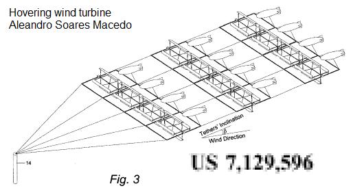
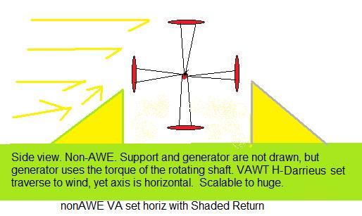
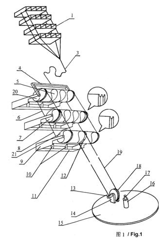 (WO
2008/101390) A METHOD AND A SPECIAL EQUIPMENT CONVERTING WIND ENERGY AT HIGH
ALTITUDE INTO KINETIC ENERGY ON THE GROUND 28.08.2008 F23D 9/00
PCT/CN2008/000255
(WO
2008/101390) A METHOD AND A SPECIAL EQUIPMENT CONVERTING WIND ENERGY AT HIGH
ALTITUDE INTO KINETIC ENERGY ON THE GROUND 28.08.2008 F23D 9/00
PCT/CN2008/000255 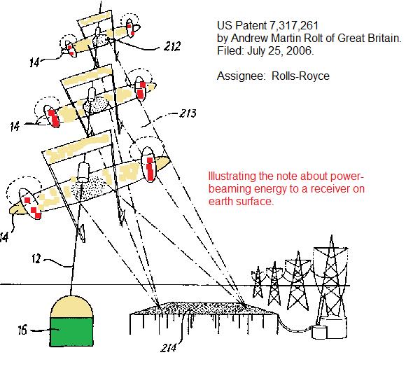


